Instrument Functions
R&S
®
NGE100B
46
User Manual 5601.1343.02 ─ 02
The four data lines of the digital I/O interface are mutually independent and can be
used as trigger input or trigger output separately. See
.
●
Trigger input
The data lines of the digital I/O interface receive external trigger signal. The exter-
nal trigger signal triggers the selected channel (Ch 1, Ch 2, Ch 3) with the set
response when the trigger condition (Active High or Active Low) is met.
●
Trigger output
The data lines of the digital I/O interface output an "Active Low" or "Active High"
signal when the trigger condition of the selected channel (Ch 1, Ch 2, Ch 3) is met.
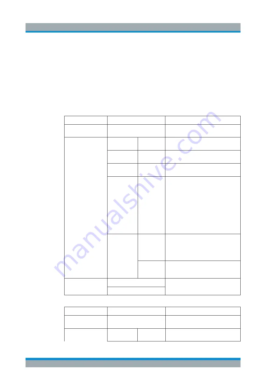
Table 5-11: Trigger in parameters and conditions
Trigger in parameters
Trigger conditions
Description
Channel
Ch 1, Ch 2, Ch 3
Target output channel selected for trigger
response.
Response Trigger
Output On
Level
Selected channel
Output
is enabled when
the selected logic level is met.
Output Off
Level
Selected channel
Output
is disabled when
the selected logic level is met.
Output Toggle
Pulse
Selected channel
Output
is toggled when
the selected logic pulse is met.
Output Inhibit
Level
Selected channel
Output
is inhibited when
the selected logic level is met.
When the selected channel
Output
is put to
inhibit state, manual or remote operation on
selected channel
Output
is no longer possi-
ble .
To reverse the inhibit state, remove the
source of the trigger signal. You can either
disable the affected DIO interface or remove
the source from the affected DIO interface at
the rear panel.
Start EasyArb
(Only for Ch 1)
Level
Activates the EasyArb function on channel 1
when the selected logic level is met. The
EasyArb is deactivated when the level
changes (i.e from active high to active low)
See
Pulse
Activates the EasyArb function on channel 1
when the selected pulse is met. See
Logic
Active High
Set the logic level of the trigger in signal.
Active Low
Table 5-12: Trigger out parameters and conditions
Trigger out parameters Trigger conditions
Description
Channel
Ch 1, Ch 2, Ch 3
Output channel selected to monitor for trig-
ger condition.
Condition Trigger
Output On
Output the selected logic level when the
Output
is turned on at the selected channel.
Advanced Functions
www.allice.de
Allice Messtechnik GmbH


