Operating Basics
R&S
®
NGL200/NGM200
39
User Manual 1178.8736.02 ─ 05
between CV and CC depending on the connected load. When CR is
, the
instrument is not switched to CR mode automatically, it will operate in CR mode when
sinking but source in CV or CC mode.
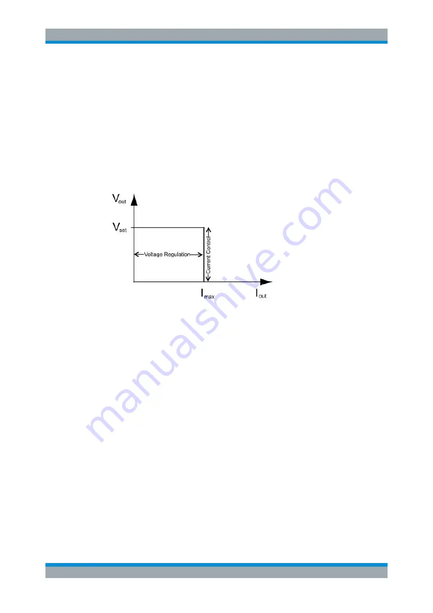
CV mode
shows that if the instrument is in the range of voltage regulation, the output
voltage V
out
remains constant while the current may increase to its maximum value I
max
when the connected load is increasing. In CV mode, the font text in the channel display
area changes to green.
See
.
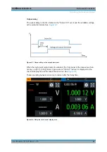
Figure 5-12: Current limit
CC mode
The current I
max
corresponds to the current setting adjustable in the instrument.
If I
out
reaches I
max
, the instrument switches to CC mode, i.e. the output current remains
constant and limited to I
max
even if the load increases. Instead, the output voltage V
out
decreases to almost zero with a short circuit. In CC mode, the font text in the channel
display area changes to red.
See
.
CR mode
To go into CR mode, the R&S
NGL/NGM must operate in sink mode where current
flows into the instrument and "Constant Resistance" is enabled.
With "Constant Resistance" enabled and configured, the R&S
NGL/NGM can set the
resistance in sink mode, this allows the R&S
NGL/NGM to behave like an electronic
load which is useful in battery test application.
In CR mode, the font text in the channel display area changes to cyan.
See
.
Operation Modes


