R&S NRP-Z27/-Z37
Connecting the sensor
1169.3870.12
1.5
E-6
Operation with the Power Meter R&S NRP/NRP2
Connecting the power sensor module
The power sensor module can be connected to the R&S NRP/NRP2 base unit when it is in operation.
The multiple circular plug-in connector must be inserted, red marking upwards, into one of the
R&S NRP/NRP2 base unit
’s sensor connectors. When the power sensor module is connected, it is
detected by the R&S NRP/NRP2 base unit and initialized.
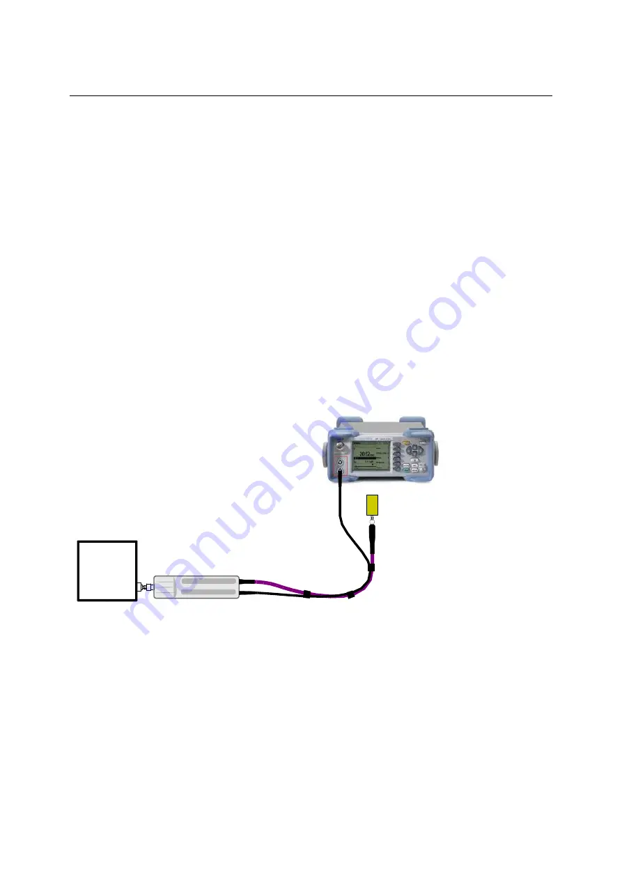
Terminate the output of the RF cable with a 3.5 mm precision termination (with female connector input).
The exact matching value is insignificant as long as the standing wave ratio of the measurement
frequency remains smaller than 1.05. Otherwise, you have to check whether the increased
measurement uncertainty can be accepted (see the
Isolation
parameter
in the specifications as well as
SENse:RGAMma
group of commands in chapter 6).
Connecting the power sensor module to the DUT
The power sensor modules have a male N connector (R&S NRP-Z27) or a male 3.5 mm connector
(R&S NRP-Z37) on their RF input and can thus be connected to any standard female N or
2.92 mm/3.5 mm/SMA connector, respectively. To connect the power sensor module to the DUT more
easily and without tilting it, relieve it by slightly lifting it.
Fig. 1-2
Configuration with the R&S NRP
Performing measurements
The R&S NRP/NRP2 handles the power sensor modules in the same manner as the thermal power
sensors of the R&S NRP-Z5x series. An exception is the S-parameter correction function, which is
always activated in the power sensor modules. This function takes the integrated power splitter into
consideration. Therefore, the influence of adapters or attenuators which are connected ahead of the
input of the power sensor module cannot be compensated via the S-parameter correction function.
However, compensation by using a global offset or an offset table is always possible.
R&S NRP-Z27/-Z37
R&S NRP/NRP2
Termination
SWR < 1.05
DUT


