Browser-Based User Interface
R&S
®
NRPxxS(N)
43
User Manual 1177.5079.02 ─ 10
Example:
To change the representation of a "Trigger Level" of 100
µ
W into dBm, enter
-10dbm
in
the "Trigger Level" field. All future entries of solely numbers represent the value in
dBm. If you enter
-15
in the field, the "Trigger Level" value is set to -15.00
dBm.
If you want to revert the value to Watt, enter
50uW
. The "Trigger Level" value is set a
value of 50.00
µ
W, thus changing the unit for the further numeric entries.
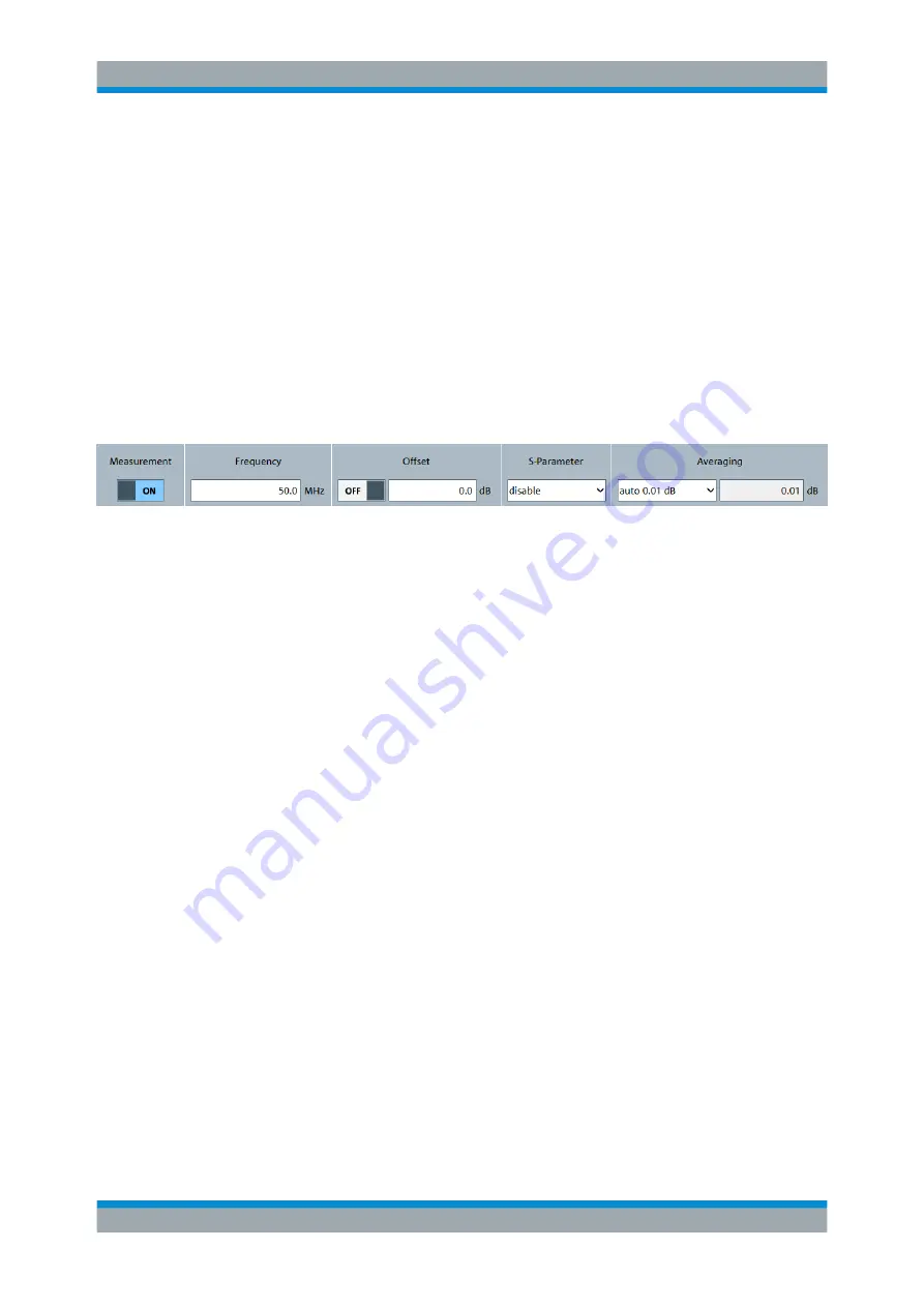
6.3
Common Settings
Describes the common sensor settings that are available for all measurement modes.
Access: main dialog of the web user interface > top pane
System Status
Displayed in the title bar. Confirms that there is a connection between the sensor and
the remote computer and that the sensor is recognized by the software.
The presentation of this symbolic LED mirrors the physical LED of the sensor. See
Measurement
Enables or disables the measurement.
Remote command:
Frequency
Sets the carrier frequency of the applied signal. This value is used for frequency-
response correction of the measurement result.
Remote command:
Offset
Groups the offset settings.
Common Settings


