Measurement Principles
R&S
®
RT
‑
ZD10/20/30
41
User Manual 1410.4550.02 ─ 05
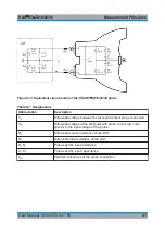
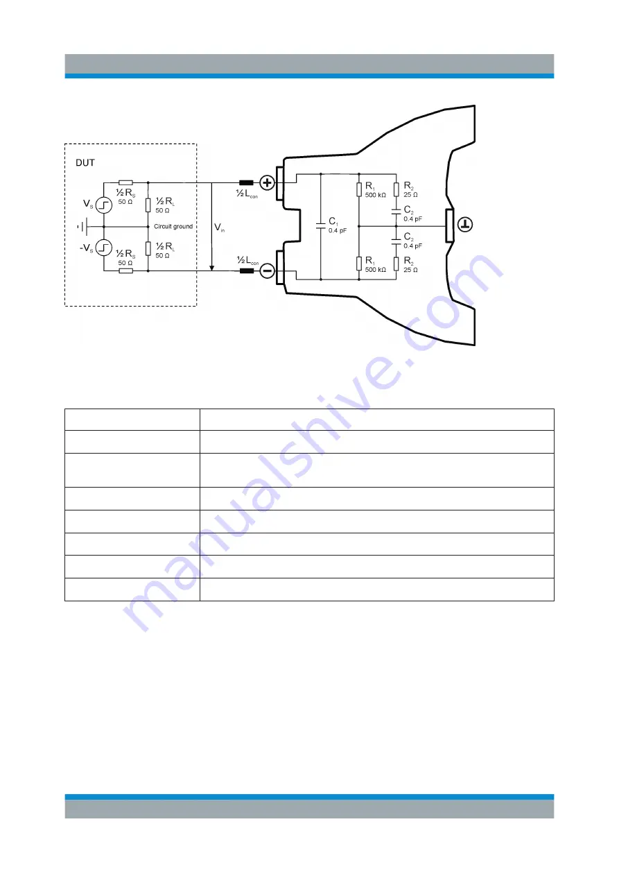
Figure 6-1: Equivalent circuit model of the R&S
RT
‑
ZD10/20/30 probe
Table 6-1: Designations
Abbreviation
Description
V
S
Differential voltage between the test point without probe connected
V
in
Differential voltage at the test point with probe connected, corre-
sponds to the input voltage of the probe
R
S
Differential source resistance of the DUT
R
L
Differential load resistance of the DUT
R
1
, R
2
Probe-specific input resistance
C
1
, C
2
Probe-specific input capacitance
L
con
Parasitic inductance of the probe connection


