Signal Generation (Option R&S
RTC-B6)
R&S
®
RTC1000
115
User Manual 1335.7352.02 ─ 02
AMPLITUDE
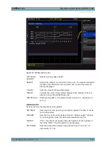
Selects the signal amplitude.
OFFSET
Selects a DC offset.
10.2 Pattern Generator
The pattern generator outputs parallel patterns on the four pins P0 to P3 on the front
panel of the instrument. It is based on a 2048-bit wide memory (samples). The pattern
can be issued cyclically or individually. It is not possible to issue multiple patterns
simultaneously.
To activate the pattern generator
1. Press the UTIL key in the Vertical section.
2. Press "PATTERN GEN.".
3. Select the pattern.
An information box shows which pins to use.
4. Adjust the settings for the selected pattern.
Table 10-1: Settings for the pattern generator
Pattern
Settings
Square wave
Frequency, polarity, duty cycle
Counter
Frequency, counting direction
Arbitrary
Timing, pattern input
Manual
Manual switching of the 4 individual connectors
UART
Polarity, bit rate
SPI / I
2
C / CAN / LIN
Bit rate
10.2.1 Square Wave
You can use "SQUARE WAVE" to perform a manual probe compensation without com-
pensation wizard. The square wave function uses a 100-sample wide pattern (100 con-
ditions). Also, you can change the polarity and the duty cycle (1% to 99%).
10.2.2 Counter
A 4-bit wide counter-pattern is issued. You can determine the counting direction and
the frequency. The frequency always refers to the switching of the pattern condition.
This results in square waveforms at the individual pins, as described in
Pattern Generator


