Serial Bus Analysis
R&S
®
RTC1000
134
User Manual 1335.7352.02 ─ 02
The oscilloscope triggers on the condition. For measurements without measuring
object, refer to chapter
Chapter 10.2.5, "Serial Buses"
FRAME START
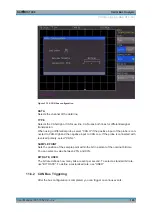
Triggers on the start of the frame. The frame starts when the chip select ("CS") signal
switches to the selected active mode, or when the time-out exceeded, at the next clock
edge.
FRAME END
Triggers on the end of the frame. The frame ends when the chip select ("CS") signal
switches from the selected active to the inactive mode, or when the time-out exceeded.
BIT
Triggers on the selected bit within the bit sequence. Use the UNIVERSAL knob or the
KEYPAD to set the bit number.
SER. PATTERN
Triggers on a specific bit pattern at a given position in the frame.
BIT OFFSET ← SER. PATTERN
Defines the position of the first bit of the configured bit sequence within the frame. The
bits in front of it have no impact on the trigger event. For example, if the bit offset = 2,
bit 0 and bit 1 after CS are ignored and the pattern begins with bit 2. You can select a
value between 0 and 4095 using the UNIVERSAL knob or the KEYPAD.
NUMBER OF BITS ← SER. PATTERN
Sets the number of bits are analyzed for the trigger condition. You can select a value
between 1 bit and 32 bit.
PATTERN INPUT ← SER. PATTERN
See
11.4.3 SPI / SSPI Decode Results
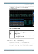
Certain parts of the SPI/SSPI messages are displayed in color to distinguish between
the different elements:
●
White: Start / End of complete frame
●
Red: Incomplete word that is not contained in the acquisition; change the horizontal
scale or move the "Time Reference" to get a longer acquisition
●
Cyan: Decoded words
SPI / SSPI BUS (Option R&S
RTC-K1)


