Analysis
R&S
®
RTC1000
79
User Manual 1335.7352.02 ─ 02
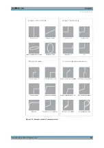
form factor of the ellipse are determined by the apparent impedance at 50 Hz (resp.
200 Hz).
●
An ellipse with horizontal long axis indicates a high impedance (small capacitance
or large inductance).
●
An ellipse with vertical long axis indicates a low impedance (large capacitance or
small inductance).
●
An ellipse with slanted long axis indicates a relatively large resistive loss in series
with the impedance of the capacitor or inductor.
When testing semiconductors, the transition from the non-conducting to the conducting
state is indicated in their characteristic. As far as is possible, with the available vol-
tages and currents, the forward and backward characteristics are displayed (e.g. with
zener diodes up to 9 V). Because this is a two-pole measurement, the gain of a transis-
tor cannot be determined, however, the B-C, B-E, C-E diodes can be measured. With
this exception, the diodes can be measured without fear of destruction as the maxi-
mum voltage is limited to 9 V and the current to a few mA. This implies, however, that
a measurement of breakdown voltages > 9 V is not possible. This is no disadvantage
because, if there is a defect in a circuit, gross deviations are to be expected which
point to the defective component. Rather exact results can be achieved if the measure-
ments are compared to those of intact components. This is especially true for semicon-
ductors. The polarity of diodes or transistors can thus be identified if the lettering or
marking is missing. Please note that with semiconductors changing the polarity causes
the display to rotate 180 degrees around the screen center. More important in practice
is the quick determination of plain shorts and opens which are the most common cau-
ses of requiring service.
Component Test

