Varying the RF Signal in List or Sweep Mode
R&S
®
SMA100B
120
User Manual 1178.3834.02 ─ 03
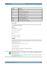
Sweep steps
In the following, you see how the sweep steps are calculated depending on the defined
spacing mode. The formulas show a frequency sweep, but apply to the level settings in
the same way.
The step width is added to the current value, to get the subsequent sweep step.
With
linear
scaling, the next frequency is calculated according to:
f
2
= f
1
+ step_lin
In the
logarithmic
scaling, the step width is determined in per cent, as a constant frac-
tion of the current frequency.
Successive frequencies are calculated as follows:
●
For f
STARt
< f
STOP
f
2
= f
1
*(1 + step_log/100)
If f
2
> f
STOP
, then f
2
= f
STOP
●
For f
STARt
> f
STOP
f
2
= f
1
/(1 + step_log/100)
If f
2
< f
STOP
, then f
2
= f
STOP
With "Shape = Triangle", the frequency values on the slope from f
STOP
to f
STARt
are the
same as on the slope from f
STARt
to f
STOP
.
If you specify the number of steps within the sweep range, the step width is adjusted
according to the following correlation:
●
For
linear
sweeps and f
STARt
< f
STOP
POINts
frequency
= ((f
STARt
- f
STOP
)/step_lin) +1 = (f
SPAN
/step_lin) + 1
●
For
logarithmic
sweeps and f
STARt
< f
STOP
POINts
frequency
= ((log f
STOP
- log f
STARt
)/log step_log) +1
If step_log changes, the value of POINts is adjusted. The f
STARt
and f
STOP
values are
retained.
5.3 About List Mode
The list mode is used to generate the RF signal based on a set of predefined fre-
quency and amplitude value pairs, with individual step times. You can define the val-
ues arbitrarily, in any order and varying step sizes, within the entire configurable value
range of the instrument.
Configuration and operation of list mode signals
The parameters configuring the RF signal are defined in a list (table) and stored in a
file.
About List Mode


