Getting Started
R&S
®
SMA100B
40
User Manual 1178.3834.02 ─ 03
2.2.1.14
Clock Synthesizer Connectors
CLK SYN/CLK SYN N
Connectors for output of the clock synthesizer signal, or the inverted signal.
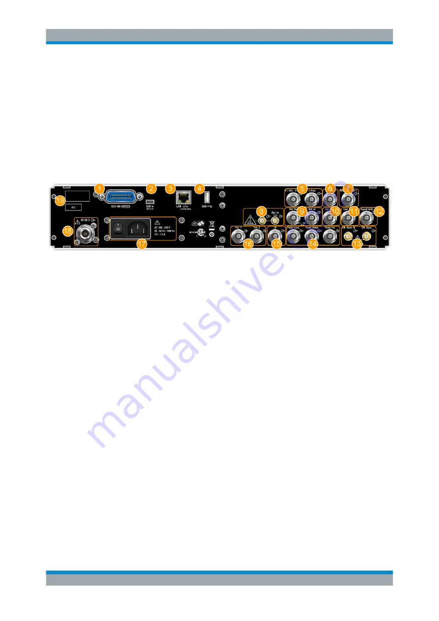
2.2.2 Rear Panel Tour
This section provides an overview of the connectors at the rear panel of the instrument.
For technical data of the connectors, refer to the data sheet.
Figure 2-4: Rear panel view of the R&S
SMA100B RF Signal Generator with height unit 2HU (option
R&S
SMAB-B92)
1 = IEC 625/IEEE 488 connector
2 = USB IN connector (type micro-B)
3 = LAN connector
4 = USB connector (type A)
5 = V/GHZ X-AXIS and Z-AXIS output connectors (BNC)
6 = STOP input and output connector (BNC)
7 = MARKER USER1 output connector (BNC)
8 = REF IN 1GHz and REF OUT 1GHz connectors (SMA)
9 = REF IN and REF OUT connectors (BNC)
10 = EFC input connector (BNC)
11 = INST TRIG input connector (BNC)
12 = SIGNAL VALID output connector (BNC)
13 = CLK SYN and CLK SYN N output connectors (SMA)
14 = PULSE SYNC, PULSE VIDEO and PULSE EXT connectors (BNC)
15 = LF output connector (BNC)
16 = EXT 1/2 input connectors (BNC)
17 = AC power supply connection and main power switch
18 = RF output connector
19 = Serial number (last six digits in the string 1419.8888.02-<serial number>)
Instrument Tour


