


Application Example: GSM AM Suppression Test
R&S
®
SMW-K550
14
User Manual 1178.3263.02 ─ 01
Simplified test setup for base station receiver testing
The
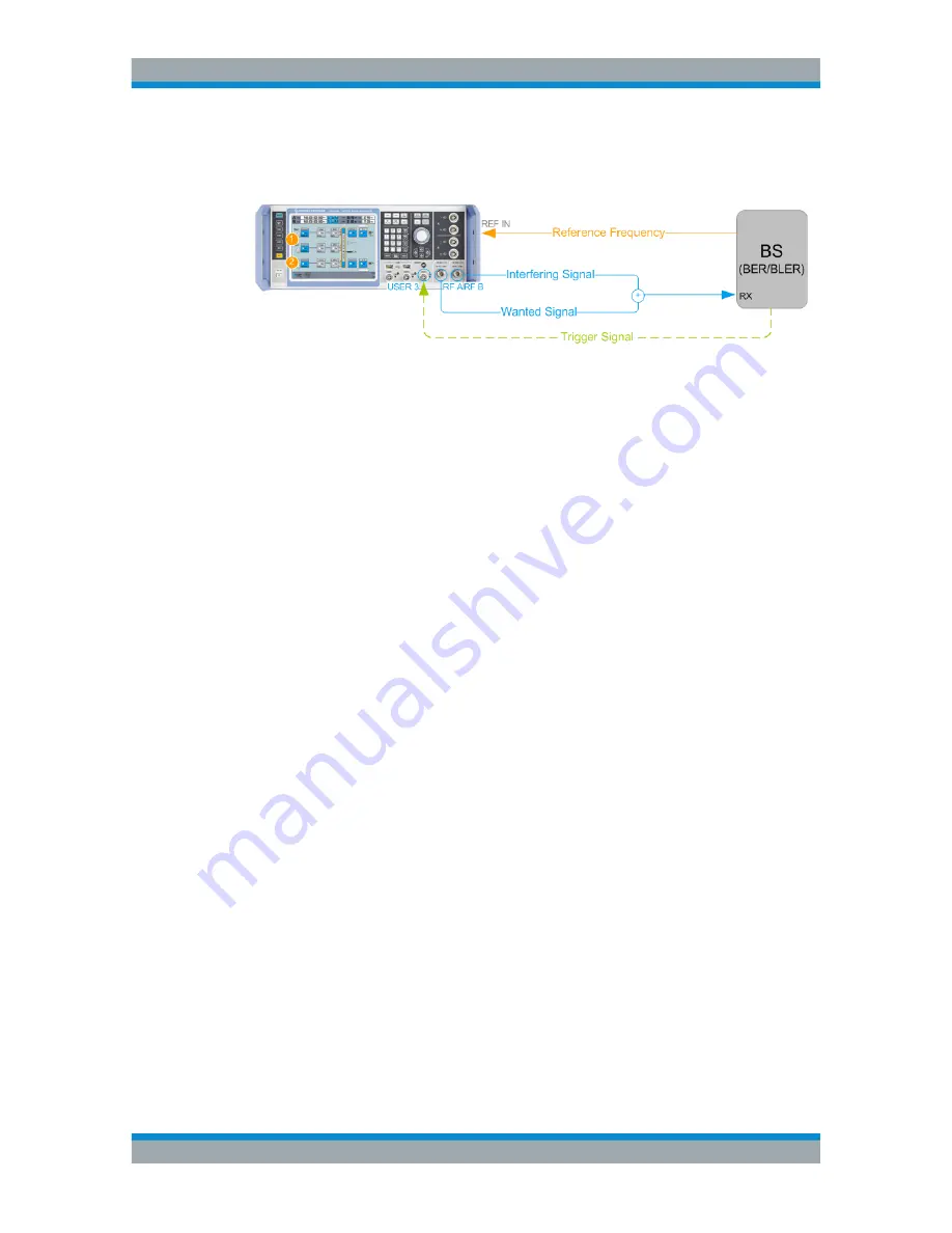
Figure 4-1
shows a simplified example of a test setup for AM suppression tests.
Figure 4-1: Simplified test setup for AM suppression tests of multi-carrier BS equipped with multi-
carrier receiver
1
= Baseband A and B generate the wanted signals
2
= Baseband C generates the interfering signal. Signal is routed to the second RF out-
put because of the difference in the power levels of the interfering and the wanted
signals (high dynamic range)
BS
= Base station
BER/BLER
= Bit error rate (BER) and block error rate (BLER) measurements
Rx
= Receiver input
Reference Fre-
quency
= 10 MHz synchronization signal form the BS to the R&S
SMW
Trigger Signal
= Optional trigger signal from the BS to the R&S
SMW
RF A,RF B,USER
= Front panel connectors
REF IN
= Rear panel connector
⊕
= RF combiner
The R&S
SMW in this setup generates four GSM wanted signals and one interfering
signal. The wanted signals are routed to and output at the RF A connector. The inter-
fering signal to the RF B connector. The interfering signal and the wanted signals are
routed to two separate RF outputs because of the difference in their power levels. Both
RF signals are connected to a combiner. The sum signal is fed to the RX input of the
BS.
The BS processes the signal and measures the bit error rate (BER) or the block error
rate (BLER). The BLER measurements require that the data sources of the GSM sig-
nal are untruncated PN sequences. The measured error performance shall not exceed
the specified limit values, where the minimum requirements are given per channel
type.
Characteristics of the wanted and the interfering signals
The wanted signals are specified as framed GSM modulated signals with specific
channel coding and low-power level.
The interfering signal is a GMSK-modulated signal with pseudo random bit sequence
of at least 511 bits length. The interferer has one active timeslot; the signal is
synchronized to and delayed in time relative to the wanted signals. The interfering sig-
nal is high in power. It does not need to have real-time data source, as no BLER mea-
surements are specified for it.
The number of wanted signals and their distribution within the maximum BS bandwidth
depends on the BS type and class. In the following, a wide area BS equipped with a
multi-carrier receiver is assumed.
About the AM Suppression Testing


