Instrument Tour
R&S
®
SZU100A
16
Manual 1425.3061.02 ─ 04
Shock hazard
The input voltage and current must not exceed the maximum values
according to the labeling or the data sheet. It is recommended that you use
the included power supply unit for the operation of the R&S
SZU.
When other than the included power supply is used to supply the equipment
with DC safety extra low voltage (SELV), the requirement for strengthened /
double insulation in line with DIN/EN/IEC 61010 (UL61010, CAN CSA
C22.2 No. 61010) or DIN/EN/IEC 60950 (UL60950, CAN CSA C22.2 No.
60950) must be met.
6.2.2
IQ Input Connectors
Input connectors for the single ended (I/Q) or differential (I/Q, I/Q BAR) baseband
signal (
, (2)).
The I/Q input connectors receive the single-ended signal, or the positive signal
components of the differential signal. The I/Q BAR connectors receive the nega-
tive signal components of the differential signal.
6.2.3
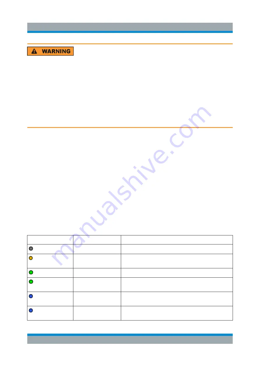
Status LED
Indicates the instrument status (
Table 6-2: The status of the R&S
SZU indicated by the color of LED
LED
R&S
SZU status
Description
off
Off
R&S
SZU is powerless.
on
Standby
Controller is running, all analog circuity are pow-
ered down.
blinking (3 Hz)
Booting or busy
Controller is booting or USB transfer is running.
on
RF Off
R&S
SZU is ready for operation with RF deactiva-
ted.
on
RF On
R&S
SZU is ready for operation with RF signal
activated.
blinking once
Trigger received
LED switches off for 200 µs when an external trig-
ger event occurred.
Rear View


