Preparing for Use
R&S
®
TSMA
24
Getting Started 1177.5604.02 ─ 10
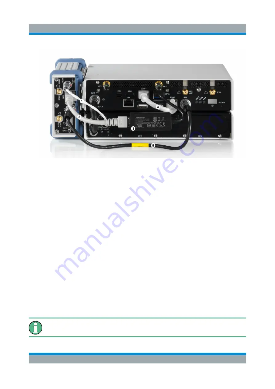
Figure 4-20: Cabling of R&S TSME with R&S TSMA
1 = Connection TSME DC IN to TSMA-BP AUX port (DC Cable TSMA-BP/TSME)
2 = Connection TSME LAN port to R&S TSPC-2UL USB 3.0 to LAN Adapter (RJ45 Patch
cable shielded CAT5E)
3 = Connection lower USB 3.0 port of the R&S TSMA (the port marked in the figure display-
ing the rear side of the combination TSMA+BP/TSME) to R&S TSPC-2UL USB 3.0 to
LAN Adapter
4 = SCAN Link interconnection cable (not included in MIMO 2x2 Upgrade Kit)
5 = Connection TSME AUX port to TSMA AUX port (SYNC Cable 2 TSME)
4.5
Connecting Test Mobile Phones
To use the R&S TSMA with test mobile phones the following steps must be per-
formed.
1. Install the driver package for the test mobile phones (see
2. Connect the test mobile phones to the USB2.0 / USB3.0 ports.
The length of the connected USB cables should not exceed 3 m.
Connecting Test Mobile Phones


