Annexes
R&S
®
ZNB/ZNBT
1554
User Manual 1173.9163.02 ─ 62
The output voltages of the RFFE and GPIO signals do not have an offset to compen-
sate additional losses into account. Please adjust the voltage level directly on your
board or at the pins of the connected device.
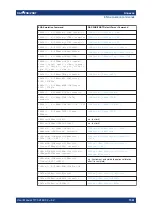
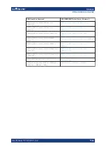
Table 12-5: Voltage/Current Measurement (Variant 03 only)
Range
Resolution
Voltage
RFFE 1 and 2
(VIO/DATA/CLK)
0 V to +3 V
100 μV
GPIO 1 to 10
-5 V to +10 V
100 μV
Current*
RFFE 1 and 2 (VIO/DATA/CLK), GPIO 1 to 8
10 Ω source resistance (shunt)
–20 mA to +20 mA
10 μA
100 Ω source resistance (shunt)
–2 mA to +2 mA
1 μA
1 kΩ source resistance (shunt)
–200 μA to +200 μA
100 nA
10 kΩ source resistance (shunt)
–20 μA to +20 μA
10 nA
100 kΩ source resistance (shunt)
–2 μA to +2 μA
1 nA
GPIO 9 and 10
–100 mA to +100 mA
10 μA
*
the current values are valid if the GPIO voltages are within -5
V to +9
V
12.4
Showroom mode
In "Showroom Mode" the R&S
ZNB/ZNBT uses a configurable recall set whenever the
device is (re-)started or the [Preset] key is pressed. However, it can only be enabled by
directly editing the Windows registry.
1. Run the R&S
ZNB/ZNBT and configure it as required for the intended showroom
operation.
2. Save the configuration as described in
Chapter 5.14.1, "Recall sets tab"
on page 669. If necessary, move the recall set file (
*.znx|*.znxml
) to the appro-
priate location.
3. Under the registry key
HKEY_LOCAL_MACHINE/SOFTWARE/Rohde-Schwarz/Vna
, create a new subkey
ShowroomMode
.
4. Within the
ShowroomMode
-subkey, create the string value
ShowroomSetup
.
Showroom mode

