Concepts and features
R&S
®
ZNB/ZNBT
203
User Manual 1173.9163.02 ─ 62
The analyzer can also auto-determine length and loss parameters, assuming that the
actual values should minimize the group delay and loss across a configurable fre-
quency range.
4.6.1.1
Definition of offset parameters
The
delay
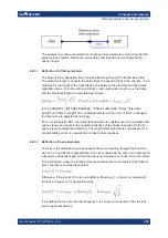
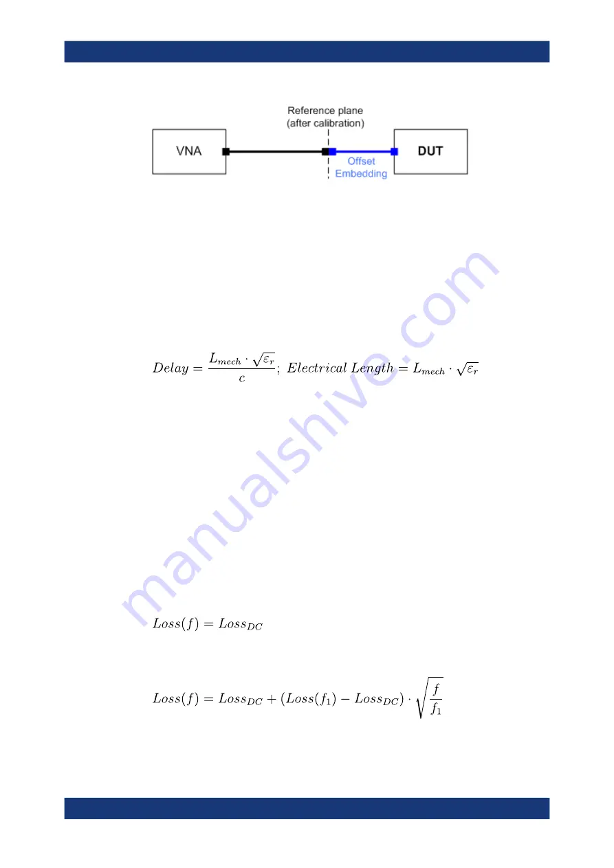
is the propagation time of a wave traveling through the transmission line.
The
electrical length
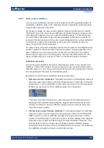
is equal to the delay times the speed of light in the vacuum. It is a
measure for the length of the transmission line between the standard and the actual
calibration plane. For a line with permittivity ε
r
and
mechanical length
L
mech
the delay
and the electrical length are calculated as follows:
In the CHANNEL – [OFFSET EMBED] > "Offset" softtool tab, "Delay","Electrical
Length" and "Mech. Length" are coupled parameters. When one of them is changed,
the other two are adjusted accordingly.
For a non-dispersive DUT, the delay defined above is constant over the considered fre-
quency range and equal to the negative derivative of the phase response for the fre-
quency (see mathematical relations). The length offset parameters compensate for a
constant delay, which is equivalent to a linear phase response.
4.6.1.2
Definition of loss parameters
The loss is the attenuation a wave experiences when traveling through the transmis-
sion line. In logarithmic representation, it can be modeled as the sum of a constant and
a frequency-dependent part, where the frequency dependence is due to the skin effect.
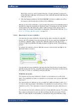
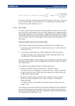
In the limit case, where the length of the transmission line is considered to be "almost
zero", the loss is considered constant:
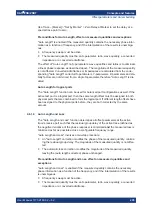
Otherwise, if the loss at DC and one additional frequency
f
1
is known (or measured),
the loss at frequency f is approximated by:
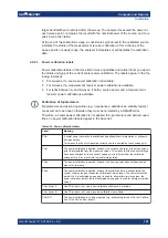
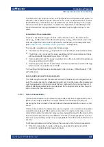
If in addition the loss at a second frequency
f
2
is known (or measured), then the loss
can be approximated by:
Offset parameters and de-/embedding

