Concepts and features
R&S
®
ZNB/ZNBT
252
User Manual 1173.9163.02 ─ 62
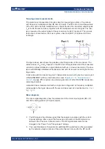
The minimum required is at least two points for every 90 degree phase angle
change in insertion loss (or 8 points per wavelength).
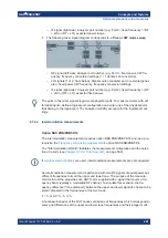
2. The "2x Thru’s" return loss must be smaller than its insertion loss.
3. The "2x Thru’s" insertion loss must be relatively linear, with a few wavelengths at
the highest frequency.
4. Use a 4-port "2x Thru" if strong far-end crosstalk (FEXT) is present.
5. Use a
complete
DUT w. fixture file for extraction.
Source: "In Situ De-Embedding (ISD) User's Guide" – November 11, 2018
4.7.10
Smart fixture de-embedding
Option R&S
ZNB-K230/R&S
ZNBT-K230
This option offers a pre-installed or service-retrofitted version of PacketMicro's
Smart
Fixture De-embedding
(SFD) for fixture de-embedding.
The tool is integrated into the de-embedding functionality of the analyzer firmware.
●
For general information about fixture de-embedding, see
●
For detailed information about the SFD tool, see the product pages at
www.packetmicro.com/Products/sfd-tool.html
.
4.7.11
Delta-L 4.0 PCB characterization
Option R&S
ZNB-K231/R&S
ZNBT-K231
Delta-L is a de-embedding methodology developed by Intel Corporation and is used for
de-embedding strip lines that include vias. Delta-L calculates the loss of PCB intercon-
nects and can be performed on single-ended or balanced interconnects.
The objective of Delta-L is to determine an insertion loss measurement defined on two
or more coupon lines of differing lengths. This ratio of insertion loss in dB/inch can be
applied to any trace length with similar vias.
For background information, see
●
●
https://ieeexplore.ieee.org/document/7048423
Optional extensions and accessories


