Concepts and features
R&S
®
ZNB/ZNBT
178
User Manual 1173.9163.02 ─ 62
Calibration kits can be obtained as network analyzer accessories; refer to the data
sheet for the relevant ordering information. The name of all parameter sets is equal to
the name of the corresponding calibration kit model.
Ideal parameters
All ideal kits contain the standards listed below.
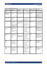
Table 4-9: Ideal standard parameters
Standard (Gender)
R (Load)
Electrical Length (Offset)
Open (f, m)
∞
Ω
0 mm (Delay: 0 s)
Short (f, m)
0 Ω
0 mm
Offset Short (f, m)
0 Ω
10 mm
Match (f, m)
Z
0
(characteristic impedance of
the connector type)
0 mm
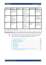
Sliding Match (f, m)
–
0 mm
Reflect (f, m)
∞
Ω
0 mm
Through (ff, mm, mf)
–
0 mm
Line (ff, mm, mf)
–
10 mm
Attenuation (ff, mm , mf)
–
0 mm
Symm. Network (ff, mm, mf)
–
0 mm
The following additional parameters are used:
●
Characteristic impedance: Z
0
(characteristic impedance of the connector type)
●
Loss: 0 dB / sqrt(GHz) or (0 GΩ / s) in Keysight mode
●
All inductance and capacitance parameters are set to zero.
4.5.2.3
Sliding Match standards
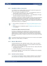
The Sliding Match is a one-port standard consisting of an air line with a movable, low-
reflection load element (sliding load). This standard is used because a no perfect
Match is available over a wide frequency range. However, a series of measurements at
a given frequency with equal mismatch and varying phase yields reflection factors that
are located on a circle in the Smith chart. The center of this circle corresponds to per-
fect match. The network analyzer determines and further corrects this match point fol-
lowing I. Kása's circle-fitting algorithm.
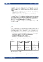
To obtain the reflection coefficient for a perfectly matched calibration standard, the Slid-
ing Match must be measured at least at 3 positions which should be unequally spaced
to avoid overlapping data points. Increasing the number of positions to 4 to 6 can
improve the accuracy. Moreover, using the predefined load positions of the standard is
recommended.
Calibration

