Concepts and features
R&S
®
ZNB/ZNBT
206
User Manual 1173.9163.02 ─ 62
The effect of "Auto Length and Loss" on S-parameters, wave quantities and ratios is to
eliminate a linear phase response and account for a loss as described above. Conver-
ted admittances or impedances are calculated from the corresponding "Auto Length
and Loss" corrected S-parameters. Y-parameters, Z-parameters and stability factors
are not derived from a single S-parameter, therefore "Auto Length and Loss" is dis-
abled.
Calculation of loss parameters
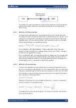
The loss is assumed to be given in terms of the DC loss Loss
DC
, the reference fre-
quency f
ref
, and the loss at the reference frequency Loss(f
ref
). The formula used in the
Auto Loss algorithm is similar to the formula for manual entry of the loss parameters
(see
Chapter 4.6.1.2, "Definition of loss parameters"
The result is calculated according to the following rules:
●
The reference frequency f
ref
is kept at its previously defined value (default: 1 GHz).
●
The DC loss c is zero except for wave quantities and for S-parameters and ratios
with maximum dB magnitude larger than –0.01 dB.
●
"Auto Length and Loss" for a wave quantity centers the corrected dB magnitude as
close as possible around 0 dBm.
●
"Auto Length and Loss" for S-parameters and ratios centers the corrected dB mag-
nitude as close as possible around 0 dB.
The resulting offset parameters are displayed in the Channel – [Offset
Embed] > "Off-
set" softtool tab.
Auto Length and Loss for balanced ports
The "Auto Length and Loss" function can be used for balanced port configurations as
well. If the active test port is a balanced (logical) port, then the same offset parameters
must be assigned to both physical ports that are combined to form the logical port. If
different offset parameters have been assigned to the physical ports before, they are
both corrected by the same amount.
4.6.1.5
Fixture Compensation
"Fixture Compensation" is an automated length offset and loss compensation for test
fixtures. The analyzer performs a one-port reflection measurement at each port,
assuming the inner contacts of the test fixtures to be terminated with an open or short
circuit.
"Fixture Compensation" complements a previous system error correction and replaces
a possible manual length offset and loss correction. For maximum accuracy, it is rec-
ommended to place the reference plane as close as possible towards the outer test fix-
ture connectors using a full n-port calibration. The "Fixture Compensation" is then car-
ried out in a second step, it only has to compensate for the effect of the test fixture con-
nections.
The following features can further improve the accuracy of the fixture compensation:
●
"Direct Compensation" provides a frequency-dependent transmission factor
(instead of a global electrical length and loss).
Offset parameters and de-/embedding

