GUI reference
R&S
®
ZNB/ZNBT
313
User Manual 1173.9163.02 ─ 62
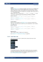
Stability
Selects a
as a measured quantity for the active trace. The stability factor
calculation is based on 2-port reflection
and
transmission S-parameters so that the
input and output port numbers must be different. The pull-down list contains all possi-
ble physical (single-ended) port combinations. For an analyzer with n ports, provides n
* (n
–
1) stability parameters.
Stability parameters are expressed as "K
<out><in>
", "μ1
<out><in>
", and "μ2
<out><in>
", where
<out> and <in> denote the logical output and input port numbers of the DUT.
Remote command:
CALCulate<Ch>:PARameter:MEASure
"<Trace_Name>", "KFAC21" |
"MUF121" | "MUF221" | ...
CALCulate<Ch>:PARameter:SDEFine
"<Trace_Name>", "KFAC21" |
"MUF121" | "MUF221" | ...
μ1 21/μ2 21/K 21
Selects one of the standard 2-port
as a measured quantity for the
active trace. These buttons are enabled if none of the logical ports 1 and 2 is defined
as a balanced port.
Remote command:
CALCulate<Ch>:PARameter:MEASure
"<Trace_Name>", "MUF121" |
"MUF221" | "KFAC21"
CALCulate<Ch>:PARameter:SDEFine
"<Trace_Name>", "MUF121" |
"MUF221" | "KFAC21"
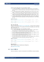
Balanced Ports...
Opens a dialog to define a balanced port configuration.
See
Chapter 5.2.1.3, "Balanced Ports dialog"
5.2.10
Power Sensor tab
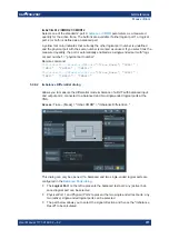
Allows you to set up and perform measurements using external power sensors.
The standard test setup for a "Power Sensor" measurement involves one analyzer
source port and a power sensor. The power sensor is connected to the VNA (e.g. to
the analyzer's USB port) and provides scalar wave quantity results. See
ter 4.7.27, "External power meters"
Meas softtool


