background image

TOUCH SCREEN WEATHER STATION MODEL 

WS-3500 


Operation Manual 


28

Summary of Contents for WS-3500

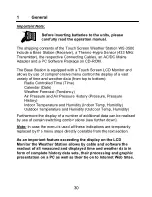
Page 1: ...TOUCH SCREEN WEATHER STATION MODEL WS 3500 Operation Manual 28...

Page 2: ...ther Tendency 8 Air Pressure History 9 Operating and Setting of various Functions 9 1 Air Pressure 10 Additional Information to Function Outdoor Temperature 11 Operating and Setting of Functions Backl...

Page 3: ...r Forecast Tendency Air Pressure and Air Pressure History Pressure Pressure History Indoor Temperature and Humidity Indoor Temp Humidity Outdoor Temperature and Humidity Outdoor Temp Humidity Furtherm...

Page 4: ...ed by use of the switching areas ON or OFF UP or DOWN or by direct unit selection Advancing to any next respective menu step with NEXT leaving or terminating all respective modes with EXIT Every progr...

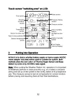
Page 5: ...th methods allow the connection of Thermo Hygro Sensor and Base Station by cable or by 433 MHz radio signal 3 Putting into Operation At first it is to decide whether battery supply or mains supply AC...

Page 6: ...connection of Thermo Hygro Sensor and Base Station can be used in case that the flexibility of 433 MHz radio transmission is not needed and data transmission absolutely free of any environmental inter...

Page 7: ...ies to an authorized depot 3 2 2 AC DC Mains Adapter Firstly also insert two Type AA 1 5 V batteries into the battery compartment of the Thermo Hygro Sensor Immediately following this connect the AC D...

Page 8: ...change and will automatically switch to the appropriate operating mode 3 3 System Start After inserting the batteries respectively connecting the AC DC adapter the LCD of the Weather Station will for...

Page 9: ...transmission they can mostly be overcome by slightly moving the mounting locations Note Commonly the radio communication between receiver and transmitter in the open field reaches distances of about m...

Page 10: ...in 8 steps from 0 to 7 Default 4 Time Zone Time Zones can be set in the range from 12 to 12 hours Default 0 hours for Central Europe DCF77 Radio Controlled Clock RCC ON OFF In setting OFF the clock i...

Page 11: ...essure with regard to the local height above sea level Default 1013 0 hPa Weather Tendency Tendency Setting to a definite switching threshold 2 hPa to 4 hPa for a change in display of weather icons De...

Page 12: ...er data form non volatile buffer memory EEPROM and reset of all set and or stored values to the factory settings set prior to shipment Acknowledge with CONFIRM Note It will take about 5 minutes for th...

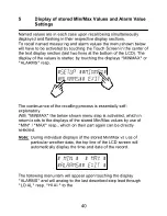
Page 13: ...g the displays MINMAX or ALARMS resp The continuance of the recalling process is essentially self explanatory With MINMAX the below shown menu step is activated which in return leads to the displays o...

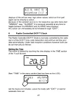
Page 14: ...ugh EXIT 6 Radio Controlled DCF77 Clock The Radio Controlled DCF77 Clock is normally controlled by the radio signal of the DCF77 time code transmitter and will thus set time and date automatically Und...

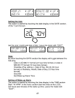
Page 15: ...ing Date in DD MM YY format 24 hour time format or Date in MM DD YY format 12 hour time format Weekday Eng abbrev Date of Day Month 24 hour format or Weekday Month Date of Day 12 hour time format Seco...

Page 16: ...the weather symbol in the TENDENCY section The text section last two lines on the LCD will show since when with time and date the weather condition corresponds to the presently displayed weather symbo...

Page 17: ...ime resolution of the bar graph can be changed from fine 0 to 24 h to coarse 0 to 72 h and back by once touching the PRESSURE HISTORY section 9 Operating and Setting of the following Functions Air Pre...

Page 18: ...hing the PRESSURE section Start with MAX in the menu section Note Display of the stored minimum values is from here possible through MIN analog to this example Display of stored value Proceed with MAX...

Page 19: ...oceed with HI AL in the menu section Note Setting of the LO alarms is from here possible through LO AL analog to this example Setting of high alarm value with UP or DOWN Proceed with ON OFF Activate o...

Page 20: ...acilities only pertain to the respective presently displayed value 11 Operating and Setting of Functions EL Backlight Light Buzzer and Alarm 11 1 EL Backlight Light For better readability of the LCD t...

Page 21: ...at have reached an alarm condition since their last deletion Here for every respective alarm the time and date of appearance can be displayed by touching ALARM 12 PC Connection As an important feature...

Page 22: ...ay of all present weather data with graphic symbols It further allows the display storage and printing of history data sets whose volume exceeding the maximum 1750 data sets of the Weather Station is...

Page 23: ...3 Data Transmission by Cable Measuring Intervals Thermo Hygro Sensor 128 s 13 4 Indoor Data Measuring Intervals Indoor Data every 20 s Temperature Range 40 C to 59 9 C Display OFL outside this range R...

Page 24: ...IEC LR6 Alkaline Batteries recommended Life Cycle approx 1 year or Power provided via Cable from the Base Station by using the AC DC Adapter 13 6 PC Connection Wiring COM Port Cable included Data Pro...

Page 25: ...ual is highly recommended for the benefit of the user This product must however not be thrown in general rubbish collection points The manufacturer and supplier cannot accept any responsibility for an...

Reviews: