
Manual-13
Time Delay Transplant
Modification
We have added modification jumpers to the AC 22. These
jumpers permit the transplanting of the Delay circuits from
one output to another. As the units are shipped, the Delay
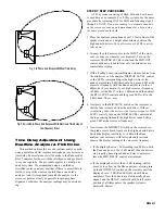
circuit is not installed on the High Frequency Outputs. When
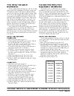
the AC 22 was first designed, long throw horns were more
common than Constant Directivity horns (CD horns). The
long throw horn's diaphragm was the farthest sound emitter
from the front of the speaker enclosure, (see Fig. 4) so no
delay was needed. The mid frequency and low frequency
drivers were always in front of the high frequency drivers,
therefore, the mid and low frequency drivers needed the
Delay circuits for proper time alignment.
Now, with the use of CD horns becoming more common,
occasionally there is a need to delay the CD horn as its
diaphragm is usually in front of the other drivers in the
enclosure (see Fig. 5). If you are using CD horns, you should
also read the CD horn EQ modification as described in the
next column.
STEP BY STEP PROCEDURE
CHANNEL ONE:
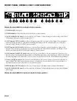
1. Refer to the board layout on page 15.
2. On the board layout locate W5 next to the CH 1 DELAY
pot, and W4 behind the CH 1 MUTE switch.
3. To remove the Delay 1 circuit from the Low Frequency
output, remove both the W5 and W4 jumpers.
4. To get the Low Frequency output to work again, place a
long jumper from W5, Pin 1 to W4 Pin 2.
5. The Delay 1 circuit is now removed from all circuits.
6. To install the Delay 1 circuit into Channel 1’s, High
Frequency output, find jumper W7 near the CH 1 INPUT
and remove it.
7. Install a long jumper from W5, Pin 2 to W7, Pin 1.
8. Install a long jumper from W4, Pin 1 to W7, Pin 2.
The Delay 1 circuit is now installed into Channel 1’s High
Frequency Output.
CHANNEL TWO:
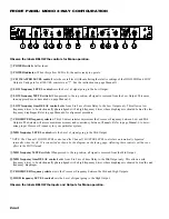
1. Refer to the board layout on page 15.
2. On the board layout locate W22 next to the DELAY pot
and W20 behind the CH 2 MUTE switch.
3. To remove the Delay 2 circuit from the Low Frequency
output, remove both the W22 and W20 jumpers.
4. To get the Low Frequency output to work again, place a
long jumper from W22, Pin 1 to W20 Pin 2.
5. The Delay 2 circuit is now removed from all circuits.
6. To install the Delay 2 circuit into Channel 2’s High
Frequency output, find jumper W25 and remove it.
7. Install a long jumper from W22, Pin 2 to W25, Pin 1.
8. Install a long jumper from W20, Pin 1 to W25, Pin 2.
The Delay 2 circuit is now installed into Channel 2 High
Frequency Output.
Constant Directivity Horn
Equalization Modification
Constant Directivity (or CD) horns need additional
equalization to help cover the same area a long throw horn
can cover. Additional circuitry has been added to the AC 22
and AC 23 layouts for the additional equalization of the High
Frequency outputs for the CD Horns. This modification
should only be attempted by an experienced technician who is
adept at soldering.
It is important to know the 3 dB down point of the CD
driver's frequency response. The manufacturer of your driver
should be able to supply you with a chart showing a fre-
quency response curve. Find the point where the high end
starts to roll off, and look for the point on the chart that is
3dB down from that point (toward the right, as the higher
frequencies roll off). Find the frequency at the bottom of the
chart of this point—an approximate is fine, you don't have to
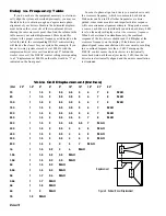
be exact. Find the closest frequency in the table below to
determine the correct value capacitor to install in the AC 22
to correct for this high frequency roll off.
STEP BY STEP PROCEDURE
The following procedure is for Stereo 2-Way. For a Mono
3-Way system with a CD horn on the high output, only place
C16 in Channel 2.
1. Remove the top and bottom covers of the AC 22.
2. Locate the positions for C15 and C16 on page 15 and on
the circuit board. C15 (for Channel 1) is located near the
CH 1 LOW OUT jack toward the middle of the board. C16
(for Channel 2) is located near the CH 2 HIGH OUT jack
toward the middle and edge of the board.
3. Clean the solder pad on the underside of the board so that
the appropriate capacitor can be inserted. Install the
capacitor, and solder the leads from the underside using
fresh solder. Clip the excess leads.
4. Replace the top and bottom covers.
3 dB Down
Frequency
Capacitor
2.2 kHz
.0027 µf
2.5 kHz
.0024 µf
2.7 kHz
.0022 µf
3.3 kHz
.0018 µf
4.0 kHz
.0015 µf
5.0 kHz
.0012 µf
6.0 kHz
.001 µf
©Rane Corporation 10802 47th Ave. W., Mukilteo WA 98275-5098 TEL (425)-355-6000 FAX (425)-347-7757 WEB http://www.rane.com
103040


