background image

Manual-5

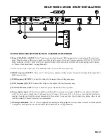
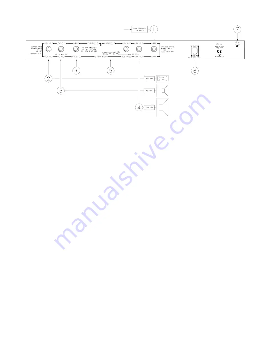
REAR PANEL: MONO 3-WAY INSTALLATION

CAUTION: MONO SUB SWITCH MUST BE IN 2-CHANNEL OR M3W MODE!


Mono (CHANNEL 1) INPUT: This ¼" Input accepts either balanced TRS (tip-ring-sleeve) or unbalanced TS (tip-sleeve)

plugs. Plug the output of the mixer, equalizer or other signal source to this Input for mono operation. DO NOT PLUG INTO
THE CHANNEL 2 INPUT: THAT INPUT IS USED TO DRIVE TWO CHANNELS WITH THE SAME MONO INPUT.
 Refer
to “Stereo 2-Way Installation” on page Manual-3.

* NOTE: Do not use this input for 3-Way Mono operation. Use the Channel 1 Input only.


HIGH frequency OUTPUT: These are ¼" TS (tip-sleeve) unbalanced Output jacks. Connect this Output to the input of the

high frequency amp.


MID frequency OUTPUT: Connect this Output to the input of the mid frequency amp.


LOW frequency OUTPUT: Connect this Output to the input of the low frequency amp.


MONO SUB mode switch: must be in the M3W position for Mono 3-Way operation.


Power input connector: This unit is supplied with a Rane RS 1 remote power supply suitable for connection to this input

jack. This unit’s power supply input is designed for an AC supply, delivering 18-24 volts, from a center-tapped transformer
capable of supplying at least the current demanded by this product. Using any other type of supply may damage the unit and
void the warranty. Consult the factory for replacement.


Chassis ground point: A #6-32 screw is supplied for chassis grounding purposes. Always connect crossover chassis ground

to amplifier chassis ground. See the CHASSIS GROUNDING note on page Manual-3.

Summary of Contents for AC 22

Page 1: ...o the CHANNEL 2 INPUT tells the unit that you are running a single channel system in Mono 3 Way mode and therefore sets the unit up to be a single channel device This can lead one to think that there...

Page 2: ...MONO SUB mode the Channel 1 LOW MUTE switch Mutes the MONO SUB Output Channel 2 s Mute is inactive LOW frequency time DELAY control adds from 0 to 2 ms of time Delay to the Low Output only This allows...

Page 3: ...LOW OUT The result is taken from the CHANNEL 1 LOW OUT jack Power input connector USE ONLY AN RS 1 OR OTHER REMOTE AC POWER SUPPLY APPROVED BY RANE This unit is supplied with a remote power supply sui...

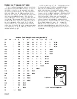
Page 4: ...This 41 detent selector determines the Crossover Frequency between Low and Mid Outputs The detents will assure maximum accuracy and consistency between Channels Refer to page Manual 6 to deter mine p...

Page 5: ...frequency amp MID frequency OUTPUT Connect this Output to the input of the mid frequency amp LOW frequency OUTPUT Connect this Output to the input of the low frequency amp MONO SUB mode switch must b...

Page 6: ...y For a detailed and enjoyable short course on time delay Linkwitz Riley and other mouth watering details we urge you to pick up free copies of the RaneNotes Linkwitz Riley Crossovers and Linkwitz Ril...

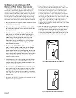
Page 7: ...from the mid driver set the analyzer DISPLAY LEVEL control so the LED s corresponding to the high crossover fre quency are reading 0 dB this would be a green LED at the crossover frequency with the R...

Page 8: ...set the output level controls as outlined on page 11 Time Delay Adjustment Using SPL Meter and Tone Generator Now that good quality realtime analyzers are becoming more affordable and easier to use th...

Page 9: ...h driver is actually in front of the mid driver adding delay to the mid driver then only worsens the situation There are a couple of ways to deal with this a Try to move the high driver back as far as...

Page 10: ...6 7 MAX 200 1 1 5 2 2 5 3 5 5 6 7 MAX 250 1 1 5 2 2 5 3 5 5 7 8 MAX 300 1 1 5 2 2 5 3 5 5 5 7 MAX 400 1 1 5 2 2 5 4 6 8 MAX 450 1 1 5 2 2 5 4 6 8 MAX 500 1 1 5 2 2 5 4 6 8 MAX 800 1 1 5 2 3 5 7 MAX lk...

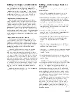
Page 11: ...e a few recommended methods of setting crossover output Levels Setting Levels Using a Realtime Analyzer NOTE If you are running two channels tune up only one channel at a time 1 Set all LEVEL controls...

Page 12: ...response 1 Run pink noise into the crossover inputs through the mixer or directly as is convenient 2 Make sure all crossover output LEVELs are turned all the way down and all amplifier level controls...

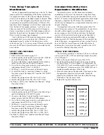
Page 13: ...circuits 6 To install the Delay 2 circuit into Channel 2 s High Frequency output find jumper W25 and remove it 7 Install a long jumper from W22 Pin 2 to W25 Pin 1 8 Install a long jumper from W20 Pin...

Reviews: