
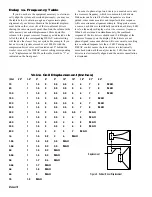
Manual-7
Time Delay Adjustment Using
Realtime Analyzer & Pink Noise
This method outlines the use of a realtime analyzer, pink
noise generator and flat response microphone to set crossover
time delay. Some references will be made to the Rane model
RA 27 analyzer for those with the intelligence and good taste
to use one regularly. The procedure applies to virtually any
analyzer system. We recommend using a one-third or
two-thirds octave analyzer as either of these is more likely to
match your specific crossover points than a one-octave
analyzer. And it is important to match the analyzer to the
crossover point as closely as possible for proper phase
alignment, otherwise the analyzer readings may be mislead-
ing.
STEP BY STEP PROCEDURE
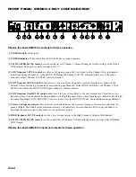
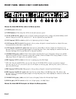
A 3-Way mode consisting of High, Mid and Low drivers
is used here as an example. For 2-Way systems, use the same
procedure by replacing LOW for MID and following steps 2
through 5. NOTE: If you are running two separate channels
on the crossover, tune up only one channel at a time, using
the same procedure for both.
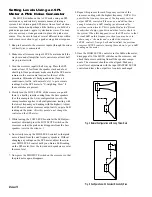
1. Place the analyzer microphone about 15 feet in front of the
speaker stack and at a height about midway between the
high and mid drivers. Turn all crossover LEVEL controls
fully down.
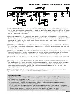
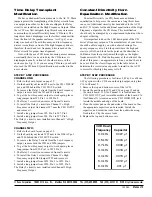
2. Connect the pink noise source to the INPUT of the cross-
over (or mixer or wherever is convenient). Turn up the
crossover MASTER LEVEL control and the MID OUT
control until noise is heard from only the mid driver at a
comfortable volume.
3. With a healthy but not uncomfortable volume of noise from
the mid driver, set the analyzer DISPLAY LEVEL control
so the LED’s corresponding to the high crossover fre-
quency are reading 0 dB (this would be a green LED at the
crossover frequency with the Rane analyzer set in the ±1
dB mode.) For example, if your high crossover frequency
is 2 kHz, set the RA 27 in the ±1 dB mode and then adjust
the RTA LEVEL control until the green LED is lit in the
2 kHz band. There... easy.
4. Now press in the MID MUTE switch on the crossover so
that the tone is removed from the mid driver. Without
re-adjusting either the meter or the crossover input or MID
LEVEL controls, turn up the HIGH LEVEL control until
the tone coming from only the high driver reads 0 dB (a
green LED at the crossover frequency).
5. Now release the MID MUTE switch on the crossover so
that pink noise is heard from both the high and mid drivers.
Switch the display sensitivity to ±3 dB on the Rane
analyzer (not necessary with full scale analyzers) and
observe the display reading at the crossover frequency:
i. If the display shows a +3 dB reading (red LED on with
the Rane analyzer in the +3 dB mode), then the drivers
are properly phase aligned and no delay is necessary;
leave the MID DELAY control at minimum.
ii. If the display shows less than +3 dB reading (still in
green or in yellow on the Rane analyzer), slowing turn
up the MID DELAY control on the crossover until the
display shows +3 dB (Red LED just on with Rane
analyzers). Now the drivers are electronically phase
aligned and the DELAY control should be left in this
position at all times unless the speaker system is
physically altered.
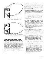
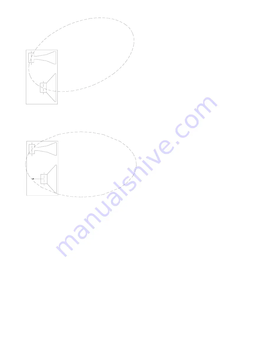
Fig. 1 In-Phase Axis Response Without Time Delay
Fig. 2 Corrected In-Phase Axis Response With Electronic Time Delay on
Low Frequency Driver


