


VI. SYSTEM CONNECTION
If you have already read the first two pages of this manual, the following will seem redundant. It
is, however, of the utmost importance that the user totally comprehend the interconnect
requirements of any piece of equipment. It is for this reason that the people at Rane don’t
mind saying this twice. It can never be said too often.
Failure to interconnect audio components properly is the number one leading cause of
problems and nasty noises. The rules are really very simple, and the following procedures will
work equally well in both balanced and unbalanced situations. The real advantage to
operating a system in the balanced mode is the lack of necessityto connect ground references
between two units. These ground connections only increase the risk of creating ground loops.
If the various components are properly connected to a pipe ground or a similar earth
connection through their 3rd pin in the line cord, intercomponent signal grounding is
unnecessary.
In the unbalanced mode, it becomes necessary to string the signal grounds between units.
When this is done, it is
imperative
that all shielding be done using chassis ground and not signal
ground. Even in the balanced mode, chassis ground should always be used for the purposes of
shielding to prevent loops.
For further information on this subject, obtain a copy of Rane Note 110 on the science of
system interconnect. It is really quite revealing.
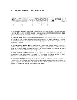
Back to the AD 13 specifically, the 3-pin input and output connectors use the same wiring
configuration for all pins. Pin 2 is always the positive connection in Rane products (per IEC 258
and ANSI PH7.102-1983), pin 3 is inverted (negative) and pin 1 is signal ground. Be sure to
check out the units to which you are connecting the AD 13 since manufacturers seem to have
difficulty agreeing on the standard or even recognizingthat it exists. Some use 3 as hot and 2 as
negative, however there are no other versions of this scheme known to us. If the worst happens
and you cannot determine the pinout of an alien unit, the most that will happen is that the
signal will be inverted in the connection. This will not cause any problems, especially if no one
knows that it is inverted. Some will claim to be able to hear the difference, if they know that it
has occurred. (If you are connecting a stereo system ignore the preceding.)
Unbalanced operation simply requires that you tie pin 2 to the hot lead, pin 1 to the signal
ground lead and shield to
case
only. Be sure to leave pin 3 open on outputs and tie it to pin 1 on
inputs. Connecting it to ground or to pin 2 on the output connector will cause excessive
current to flow and disrupt signal fidelity. This will cause no damage to the AD 13, only to your
signal path.
When using the barrier strip, there can be little confusion as to the proper connection practice,
thanks to the clear legends printed above and below the connectors. Again, + to +, – to –, and
signal ground is not required unless unbalanced operation is required. If the latter is the case,
do not
use signal ground for shielding. Use chassis ground only for connecting shields for
unbalanced operation.
Once the wiring is completed, one must make the choice between active or transformer
output operation. There are as many sides to this issue as there are to any other controversial
topic. We prefer to lean toward the school of common sense which dictates that if you have
unsolvable problems in one mode of operation which are solved by switching to the other,
then do so. If you have difficulties in neither mode, then let your personal preference guide
your actions. Wasn’t that easy?


