background image

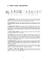
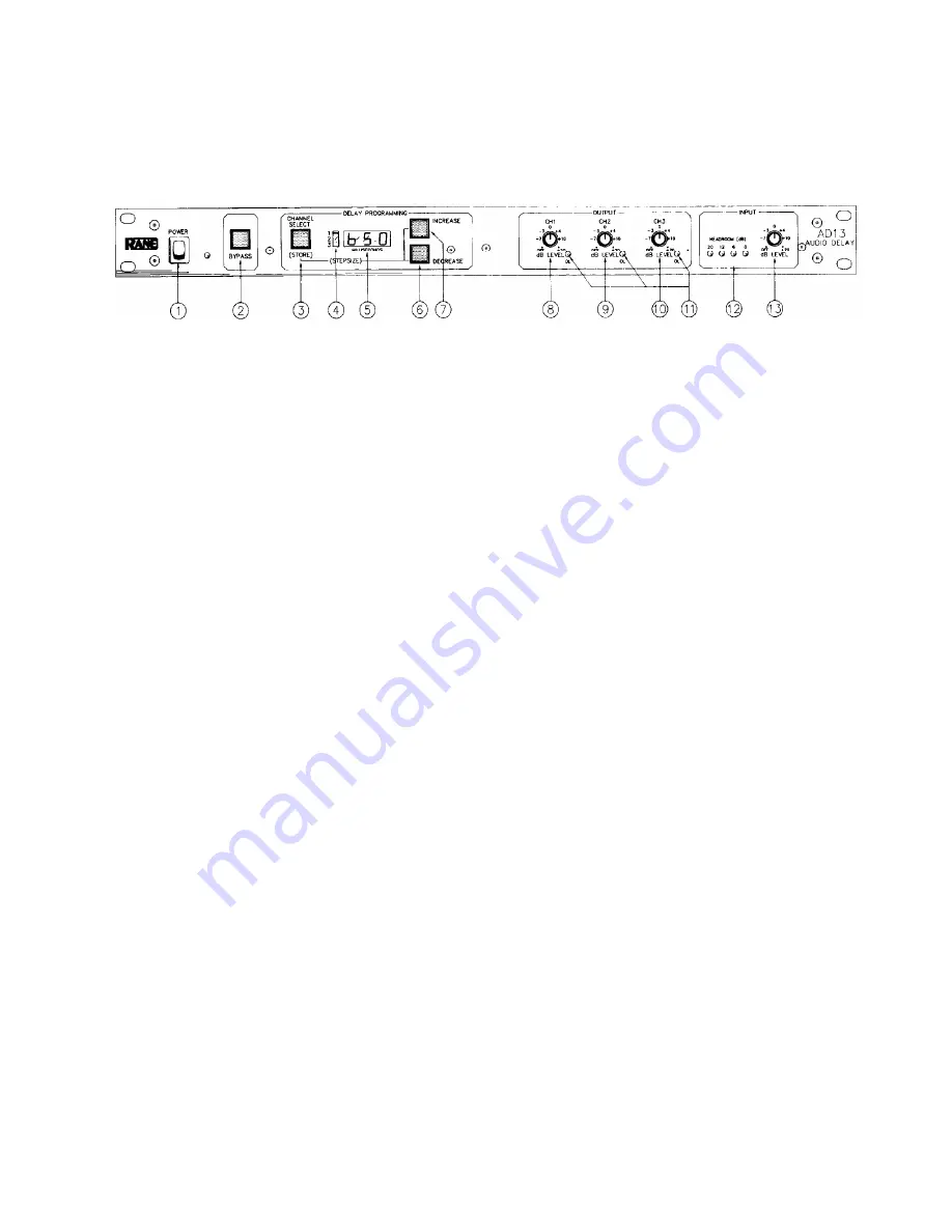
II. FRONT PANEL DESCRIPTION

1. POWER SWITCH: 

Pressing the top half of this switch will cause the mechanism contained

within to connect power to the circuitry of the unit causing it to operate (ON). Pressing the

bottom half will snap the switch into the opposite operating mode (OFF).

2. BYPASS SWITCH: 

Pressing this momentary pushbutton toggles all of the outputs of the AD

13 between the active and bypass mode. Bypass is indicated on the LED display by an “OFF”
indication.

3. CHANNEL SELECT SWITCH: 

Pressing this momentary pushbutton advances the output

channel pointer by one increment which simultaneously displays the delay setting of the
selected channel on the LED display. THIS BUTTON ALSO CAUSESTHE DELAY SETTING OF

THE PREVIOUSLY SELECTED CHANNELTO BE STORED IN THE NON-VOLATILE MEMORY

OF THE AD 13.

4. OUTPUT CHANNEL POINTER: 

This LED pointer alerts the operator to the channel number

currently being displayed by the LED display.

5. LED DISPLAY: 

The primary purpose of this display is to inform the user as to the amount of

delay currently applied to any of the three outputs, these outputs being selected by the
channel select switch and pointed to by the LED channel pointer to its left. The display also

indicates overall bypass by an “OFF” indication and can be used to display the software
revision of the system while in the bypass mode by holding the channel select button down
and pressing the “DECREASE” switch.

6. DECREASE BUTTON: 

Pressing this button will decrease the amount of delay on the selected

channel. PRESSING THE CHANNEL SELECT BUTTON WHILE THE DECREASE BUTTON IS
HELD WILL TOGGLE BETWEEN THE 20 MICROSECOND DELAY STEPS AND 1 MILLI-
SECOND DELAY STEPS.

7. INCREASE BUTTON: 

Pressing this button will increase the amount of delay on the selected

channel. Pressing the channel select button while the increase button is held will toggle

between 20 microsecond delay steps and 1 millisecond delay steps.

8. CHANNEL 1 OUTPUT LEVEL CONTROL: 

This rotary control varies the output level of

channel 1 from “off” at its full counterclockwise position to unity at its center detent “12:00”
position to +20 dB at its full clockwise position.

3

Summary of Contents for AD 13

Page 1: ......

Page 2: ......

Page 3: ...he Rane factory before taking it anywhere for repairs We will help you to identify and locate any specific malfunctions possibly avoid needless shipment or instruct you as to the speediest method for...

Page 4: ...his display is to inform the user as to the amount of delay currently applied to any of the three outputs these outputs being selected by the channel select switch and pointed to by the LED channel po...

Page 5: ...any of the respective output stages approach this sort of difficulty 12 lNPUT HEADROOM INDICATOR These four LEDs will illuminate at the appropriate times to indicate whetherthere is 20dB 12dB 6dB or...

Page 6: ...IN to their locked position places the respective output stage into its transformer balanced mode Pressing the switch again to release it from its IN position causes the output to be placed back into...

Page 7: ...a of the original signal All seriousness aside it really is almost that simple If you ve ever seen an audio waveform play in real time on an oscilloscope you have probably thought that it looked impos...

Page 8: ...response to flat The lower high frequency sensitivity at the output results in a lower output noise level The next stop on the tour is the input level control From the input level control the signal...

Page 9: ...0 microsecond real time interval from 0 to 654 milliseconds after it has been stored All three of the digital to analog converters has access to the data at any time within the boundaries of the maxim...

Page 10: ...check out the units to which you are connecting the AD 13 since manufacturers seem to have difficulty agreeing on the standard or even recognizingthat it exists Some use 3 as hot and 2 as negative how...

Page 11: ...front of the hall and auxiliary reinforcement 40 feet to the rear would require approximately 40 milliseconds of delay on the rear speakers for maximum intelligibility Some experimentation will be re...

Page 12: ...he chain No matter what sort of mixer processor or amplifier you are using gain at the front end will yield the lowest overall noise SETTING LEVELS With most power amplifiers you should find that with...

Page 13: ...tisfies VDE0871 for Class A computing devices RESIDUAL PROPAGATION DELAY 190 s INTERMODULATION DISTORTION SMPTE less than 0 1 4dBu THD NOISE less than 0 l 20 20kHz 4dBu unity gain SIGNAL TO NOISE RATI...

Reviews: