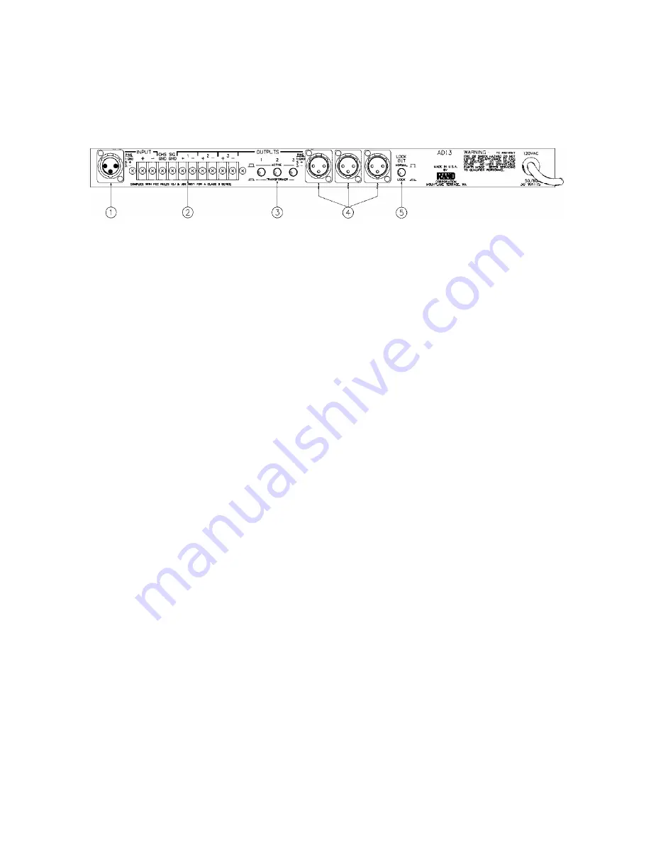
III. REAR PANEL DESCRIPTION
1. 3-PIN INPUT CONNECTOR:
This is a differential active balanced input, connected such that
pin 2 is HOT, pin 3 is RETURN, and pin 1 is signal ground, NOT SHIELD GROUND. Shield
ground should only be connected to the case of the connector.
2. BARRIER STRIP INPUT AND OUTPUT CONNECTOR:
From left to right, the connections are
as follows: + input, – input, input signal ground, channel 1 “+” output, channel 1 “–” output,
channel 2 “+” output, channel 2 “–” output, output signal ground, channel 3 “+” output and finally,
channel 3 “–” output.
3. ACTIVE/TRANSFORMER SELECT SWITCHES:
Pressing any of these switches “IN” to their
locked position places the respective output stage into its transformer balanced mode.
Pressing the switch again to release it from its “IN” position causes the output to be placed
back into its active balanced output configuration.
4. 3-PIN OUTPUT CONNECTORS:
These are differential active balanced outputs, Pin 1 is
connected to signal ground, Pin 2 is the positive “+” output and Pin 3 is the negative “–” output,
The case is considered Pin 4 and should be used for shield terminations.
5. LOCK-OUT SWITCH:
Pressing this switch to its “IN” and locked position prevents the
“INCREASE”,” DECREASE” and “BYPASS” buttons on the front panel from changing any of the
preset programs. The “CHANNEL SELECT” button will still operate allowing anyone who
passes by to view the settings of all three of the delays.


