Manual-3
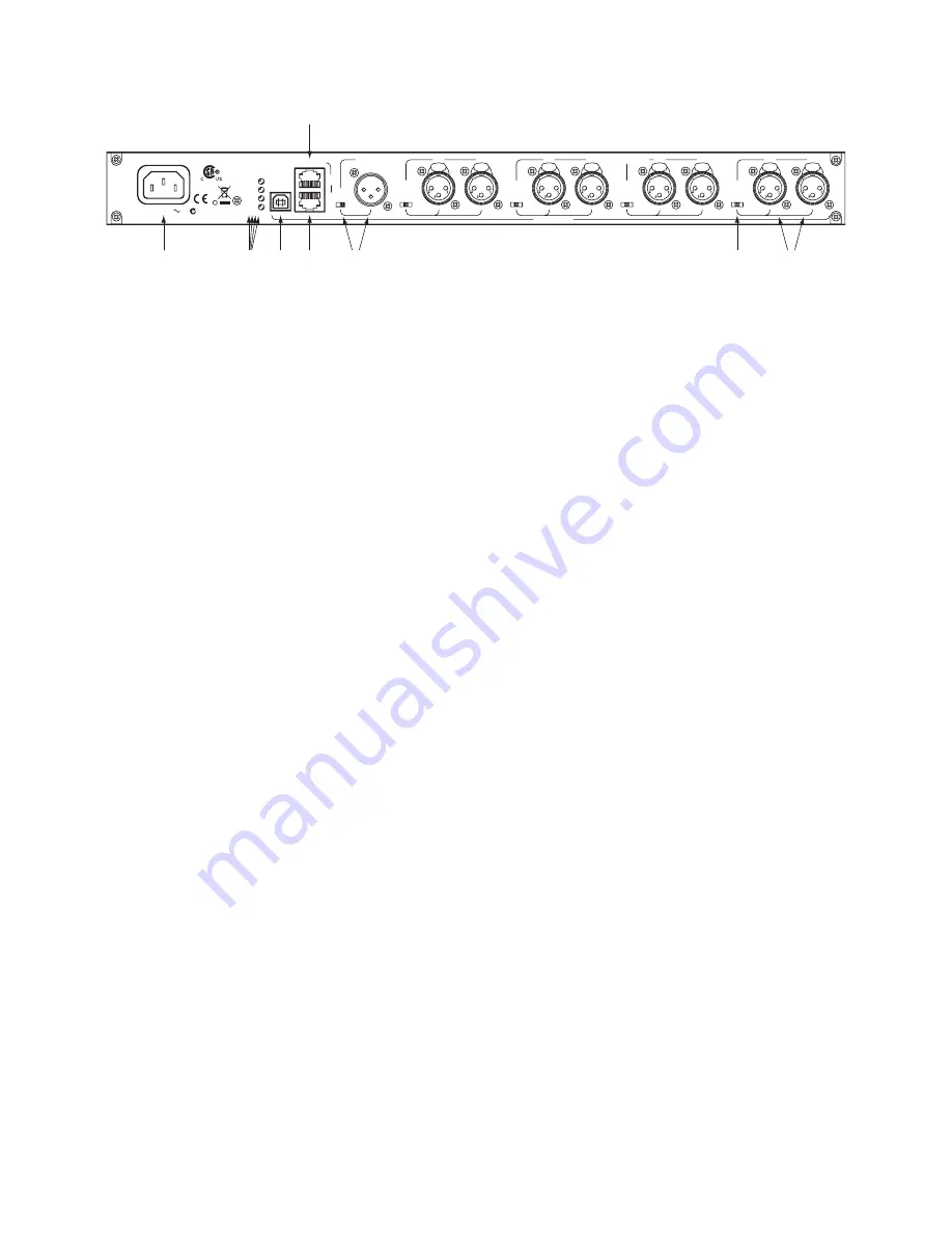
REAR PANEL DESCRIPTION
1
AC Power IEC input
accepts electrons to power up the AM2. Though it is first in this list, it’s best to connect it last.
2
FAULT
indicator
lights when something goes awry.
LOCATE
indicator
flashes when toggled from the Mongoose Tracker software. When using multiple AM2 devices in a
Rane Mongoose-based CobraNet™ system, this uniquely identifies a specific AM2.
USB
indicator
lights when a Windows or Apple operating system recognizes the AM2 for firmware updating.
POWER
indicator
glows when flowing electrons pass in and out of the AC Power IEC input.
3
USB DATA
connector
allows updating the AM2 firmware should a future need arise. Firmware updates are made available on the
AM2 page at
www.rane.com/am2.html
.
4
CASCADE IN
port
permits adding up to 56 more microphones to the AM2’s eight mic inputs using up to seven Rane AM2
automixers, sold separately. Use shielded Ethernet CAT 5 cable connected from the AM2’s CASCADE OUT. See the Connection
section for details.
5
One jack, two functions:
The
CASCADE OUT
connects to an AM1 or another AM2’s CASCADE IN when combining units
for more gain-sharing mics. The
RAD PORT
connects to a Rane Mongoose’s Remote Audio Device port to transport the single-
channel, Main Mix of the AM2 to a CobraNet network or another Remote Audio Device.
6
MAIN OUTPUT
XLR connector
contains the main mix of all mics from this AM2, and all mics from preceding AM2s, if they
are connected using the CASCADE ports. The front panel OUTPUT LEVEL control adjusts the level exiting this jack.
MIC/LINE
Output switch
changes this Main XLR Output to mic-level, for feeding the output mix to a mic input device; or
line-level for feeding line-level input devices.
7
3-position
MIC/LINE
switches
support 48 volt phantom power Mic position for condenser mics, zero volt Mic position for
dynamic mics, and the Line position intended for wireless mic receiver outputs. Each switch controls a pair of mic inputs, as
indicated by the rear panel grouping of two jacks for one switch.
8
MIC INPUTS 1
thru
8
accept dynamic or condenser microphones, or the output of a wireless microphone receiver. These inputs
are optimized for speech and have a fixed 100 Hz low-cut and 7 kHz high-cut filter. Both filters are 2nd-order Butterworth filters.
CASCADE
RAD PORT
USB
DATA
OUTPUT
MIC INPUTS
1
2
3
4
5
6
7
8
100-240V
13 WATTS
50/60 Hz
MADE IN
U.S.A.
RANE CORP.
ACN 001 345 482
AM2
MIC +48V MIC +0V LINE
MIC +48V MIC +0V LINE
MIC +48V MIC +0V LINE
MIC +48V MIC +0V LINE
IN
OUT
USB
LOCATE
FAULT
POWER
THIS DEVICE COMPLIES
WITH PART 15 OF THE FCC
RULES FOR A CLASS 'B'
COMPUTING DEVICE.
24 VDC @ 100 mA
CLASS 2 WIRING
MIC LINE
1
2 3
4
5 6
8
7


