Manual-1
OPERATORS MANUAL
CP 31
COMMERCIAL PROCESSOR
QUICK START
If you were the type that cheated on school book reports by just skimming through the reading assignments, then this
section is for you! It gives you not quite enough information to
really
know what you’re doing. But, if you follow the
recommended set up procedure, you should get at least a “B.” This thing is pretty easy to set up…a “C” will pass.
Keep the amplifiers and the CP 31 turned
off
until all connections are made. The unit does
not
ground the chassis
through the power cord.
It is important that the unit be grounded (required by law in most installations).
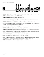
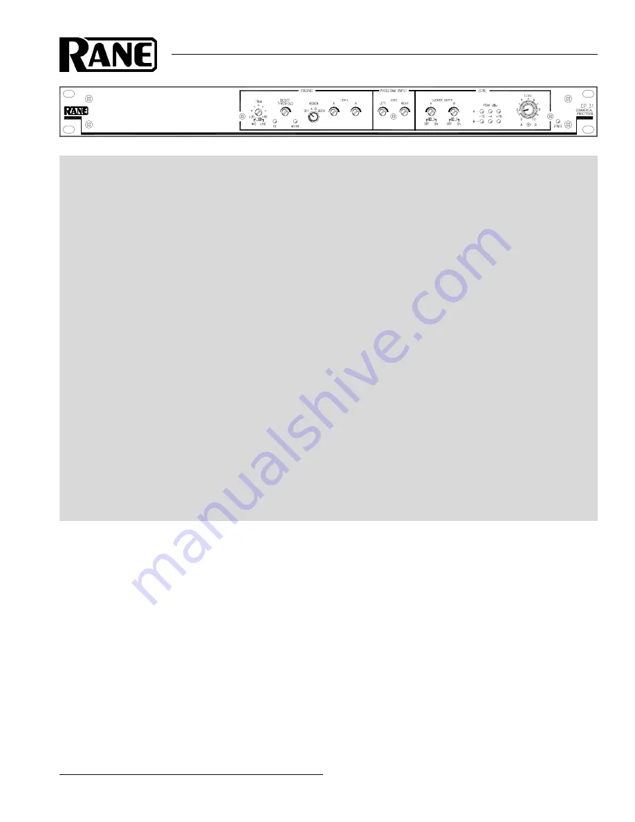
PAGE INPUT:
Connect the
PAGING INPUT
to the Euroblock on the rear panel. On the front, select the appropriate
MIC
or
LINE
switch position. Then set the gain with the
PAGING TRIM
control, then set the
PAGING DETECT THRESH-
OLD
and finally the
PAGING LEVEL
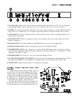
. Set the
HIGH/LOW CUT FILTER
switch located on the rear panel as desired.
PROGRAM INPUTS:
Connect line level program sources to the
RCA PROGRAM INPUT
jacks and engage the
MONO
switch if desired. Set the
PROGRAM INPUT LEVELS
.
EXPAND OUTPUT:
Wire the
EXPAND
Output Euroblock as required to a mono feed delivering
PAGE-only
or
PRO-
GRAM-only
signal, depending on the rear panel switch setting. This Output uses a line driver that may be used balanced or
unbalanced. Adjust the
EXPAND LEVEL
trim as desired.
DUCKER:
With the
DUCKER
switches
ON
, and a Program source playing, speak into the mic and adjust the
DUCKER
DEPTH
to control the Program level during a page. Program will return to its previous volume after the page has finished.
ZONE OUTPUT:
The
ZONE OUTPUT
uses a line driver that may be used balanced or unbalanced. Set the
LEVEL
control as required.
A
highly
recommended setup procedure appears on page Manual-4. By following it you will encounter fewer problems
and reduce the need to increase our collective phone bills.
CAUTION: Never connect anything except an approved Rane Power supply to the thing that looks like a red tele-
phone jack on the rear of the CP 31.
This is an 18 VAC center tapped power input. Consult the Rane factory for replacement.
CP 31 CONNECTION
Be sure the power is OFF until all connections are made.
EUROBLOCK CONNECTIONS
All Input and Output connections are made with Euro-
block connectors except for the RCA Program Inputs. When
wiring to Euroblocks, a minimum wire gauge of 22 AWG is
preferred for reliability. If the ground or shield wire is left
shorter, it acts as a strain relief for the other wires. Cable with
a flexible jacket is easier to use and less likely to damage the
connections. Avoid stripping excess insulation. Inspect wires
for nicks that may lead to wire breakage. Fully insert each
wire in the appropriate socket and tighten the screw.
The Page Input circuit is a true instrumentation amplifier
and operates balanced or unbalanced. Expand and Zone
Outputs are balanced line drivers. Wiring is usually the same
for both Inputs and Outputs. Balanced operation is highly
recommended. Balanced wiring is straight forward, (+) to (+),
(–) to (–) and shield to shield.
For unbalanced operation, use single conductor cable with
shield. Connect (+) to (+) and the shield/ground wires to the
shields at both ends. Do not connect the (–) pin. When
unbalanced wiring is used, it is very important for the CP 31
and any other unit in the system to have good earth or
technical grounds. If a unit is located far from the CP 31
(greater than ten feet) or is of a type that might create ground-
ing problems, use isolation transformers.
Refer to the included RaneNote 110, “
Sound System
Interconnection
” for more information on proper wiring
procedures.
PROGRAM INPUTS
The stereo or dual-mono Program Inputs connect to RCA
jacks. These Inputs are unbalanced. The same guidelines
given above for unbalanced operation apply to these Inputs.
WEAR PARTS:
This product contains no wear parts.

