background image

Manual-2

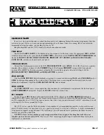
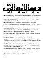
CP 52 - FRONT PANEL


PAGING TRIM

 control adjusts the Page Input preamplifier gain to match the microphone/source in use, 

not

 to set the Page

level in the Zone Output. The range is 30 dB to 60 dB.

 PAGING MIC/LINE 

switch selects a 30 dB Input Pad when set to LINE. 

Phantom Power is disabled when LINE is selected.

 PAGING DETECT THRESHOLD

 sets the Page signal level required to gate a Page 

on

 and illuminate the ACTIVE

indicator (see 

). The range is -

∞ 

(on) to +4 dBu.

 PAGING OL (Overload) 

indicator lights when the Page Input preamplifier comes within 3 dB of clipping.

 ACTIVE 

indicator lights when the Page signal level reaches the Paging Detect Threshold. 

Note that a Page is always Active

when the PAGING DETECT THRESHOLD is set to minimum (ccw).

 PAGING LEVEL 

control adjusts the Paging Level in the Zone.

 PAGING LIMIT THRESHOLD

 control sets the maximum output level for a Page. This is a true voltage Limiter circuit

with a ratio of 15:1. The Threshold range is -20 dBu to +20 dBu. The 

THRESHOLD

 indicator lights during limiting.

 PROGRAM INPUT LEVEL

 controls allow independent adjustment of level for each Program Input.


ZONE DUCKER DEPTH 

control


sets the Ducker Depth (the amount of Program attenuation during a Page) from 50 dB

(ccw) to 6 dB (cw). The Ducker 

release

 is ramped.

 ZONE DUCKER OFF/ON

 switch turns the Ducker ON or OFF.

 ZONE PROGRAM SELECT 

switch assigns one of four Program Inputs to the Zone Output.

 ZONE RMT 

switch, when pushed 

in

, turns control of Zone Level and Zone Program Selection over to the Zone Remote

Port. Front panel ZONE LEVEL and ZONE PROGRAM SELECT controls are 

inactive

 when RMT is selected. An optional

wired ZR 1 remote may be connected to the Zone Remote Port. 

An object smaller in diameter than the switch button is

required to engage the RMT switch.

 ZONE SIG/OL

 indicators show Signal present at -20 dBu and Overload at +16 dBu (4 dB before clipping) respectively.

 ZONE LEVEL 

control


adjusts the overall Level for the Zone Output. If the rear panel PAGE LEVEL TRACKS ZONE

LEVEL switch is ON, this control also effects the Paging Level.

 ZONE LIMIT THRESHOLD

 control sets the maximum level for the Zone Output. This is a true voltage Limiter circuit

with a ratio of 15:1. The Threshold range is -20 dBu to +20 dBu. The 

THRESHOLD 

indicator lights during Limiting.

 GRAPHIC EQUALIZER 

controls are “stereo,” with each slider controlling the response of both Left and Right channels.

These controls allow ±12 dB adjustment of seven ISO center frequencies on 1

1

/

3

 octave centers.

 PWR

 indicator lights when the CP 52 is connected to a powered RS 1 power supply.

Summary of Contents for CP 52

Page 1: ...ering PAGE only PROGRAM only or ZONE both signal depending on the switch setting This Output uses a cross coupled line driver and may be used balanced or unbalanced Adjust the ZONE EXPAND LEVEL trim as desired ZONE OUTPUT The ZONE OUTPUT uses a cross coupled line driver and may be used balanced or unbalanced Set the front panel LIMIT THRESHOLD as required Depress the MONO switch for a mono Zone ZR...

Page 2: ...ogram attenuation during a Page from 50 dB ccw to 6 dB cw The Ducker release is ramped 햻 ZONE DUCKER OFF ON switch turns the Ducker ON or OFF 햽 ZONE PROGRAM SELECT switch assigns one of four Program Inputs to the Zone Output 햾 ZONE RMT switch when pushed in turns control of Zone Level and Zone Program Selection over to the Zone Remote Port Front panel ZONE LEVEL and ZONE PROGRAM SELECT controls ar...

Page 3: ...urce for the Expand Output 햹 ZONE EXPAND LEVEL trim adjusts the signal level delivered to the ZONE EXPAND OUTPUT 햺 PRIORITY RELEASE TIME control sets the delay time from last detected signal to release of automatic priority over ride The range of control is 5 seconds ccw to 20 seconds cw 햻 PRIORITY OFF ON switch allows disabling the automatic priority override function when in the OFF position 햽 P...

Page 4: ...ght forward to to and shield to shield For unbalanced operation we recommend using two conductor cable with shield The cable is wired to the CP 52 the same as for balanced operation At the other end of the cable connect the wire to signal hot and both the and shield wires to ground important If you use single conductor cable with shield connect the shield gnd wire to both the and shield pins at th...

Page 5: ...he CP 52 Connect each wire to the 5 pin connector by fully inserting it in the correct socket and tightening the screw Make sure wires are free of nicks and that the cable jacket is stripped back sufficiently to allow it to lie in the electrical box with the remote assembly inserted Use the flat head 6 screws supplied with the kit to mount the remote assembly and silk screened front panel to the e...

Page 6: ...RESHOLD Min ccw Active front panel Paging LEVEL Min front panel LIMIT THRESHOLD 20 dBu front panel PHANTOM POWER As required rear panel HIGH LOW CUT FILTER As required rear panel PAGE LEVEL TRACKS ZONE LEVEL OFF rear panel PROGRAM INPUT SETTINGS Input Levels Min front panel PRIORITY DETECT THRESHOLD Set to 50 dBu at factory range to 35 dBu rear panel PRIORITY RELEASE TIME Set to 12 sec at factory ...

Page 7: ...e on due to background sound 7 With an active Program source playing speak into the Paging mic Adjust the Paging LEVEL control to provide the correct Page to Program mix If the Paging Detect Threshold is set too high there may be a delay before speech is heard To correct this lower the Paging Detect Threshold setting 8 Set the Paging LIMIT THRESHOLD to limit the maximum Page level to the loudest d...

Reviews: