background image

Manual-4

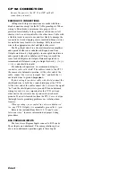
CP 52 CONNECTION

Be sure the power to the CP 52 is OFF until all
connections are made.

EUROBLOCK CONNECTIONS

All Input and Output connections are made with Euro-

block connectors except for the RCA Program Inputs. When
wiring to Euroblocks, a minimum wire gauge of 22 is
preferred for reliability. If the ground or shield wire is left
shorter, it acts as a strain relief for the other wires. Cable with
a flexible jacket is easier to use and less likely to damage the
connections. Avoid stripping excess insulation. Inspect wires
for nicks that may lead to wire breakage. Fully insert each
wire in the appropriate socket and tighten the screw.

The Page Input circuit is a true instrumentation amplifier

and operates balanced or unbalanced. Expand and Zone
Outputs are driven by high quality cross-coupled line drivers
and operate balanced or unbalanced. Wiring is usually the
same for both Inputs and Outputs. Balanced operation is
recommended. Balanced wiring is straight forward, (+) to (+),
(–) to (–) and shield to shield.

For unbalanced operation, we recommend using 

two

conductor cable with shield

. The cable is wired to the CP 52

the same as for balanced operation. At the 

other

 end of the

cable, connect the (+) wire to signal “hot,” and both the (–)

and

 shield wires to ground 

(

important

).

If you use 

single conductor cable with shield

, connect the

shield/gnd wire to both the (–) and shield pins at the CP 52.
At the 

other

 end of the cable connect the (+) wire to the signal

“hot” and the shield/gnd wire to ground. When unbalanced
wiring is used, it is very important for the CP 52 and any
other unit in the system to have good earth or technical
grounds. If a unit is located far from the CP 52 or is of a type
that might create grounding problems, use isolation trans-
formers.

When operating cross-coupled line drivers unbalanced

(i.e., any CP 52 Output)

, it is 

essential

 to ground the (–) pin.

Refer to the included RaneNote 110, “

Sound System

Interconnection

” for more information on proper wiring

procedures.

RCA PROGRAM INPUTS

The four stereo Program Inputs connect to RCA jacks.

These Inputs are unbalanced. The same guidelines given
above for unbalanced operation apply to these Inputs.

Summary of Contents for CP 52

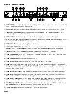
Page 1: ...ering PAGE only PROGRAM only or ZONE both signal depending on the switch setting This Output uses a cross coupled line driver and may be used balanced or unbalanced Adjust the ZONE EXPAND LEVEL trim as desired ZONE OUTPUT The ZONE OUTPUT uses a cross coupled line driver and may be used balanced or unbalanced Set the front panel LIMIT THRESHOLD as required Depress the MONO switch for a mono Zone ZR...

Page 2: ...ogram attenuation during a Page from 50 dB ccw to 6 dB cw The Ducker release is ramped 햻 ZONE DUCKER OFF ON switch turns the Ducker ON or OFF 햽 ZONE PROGRAM SELECT switch assigns one of four Program Inputs to the Zone Output 햾 ZONE RMT switch when pushed in turns control of Zone Level and Zone Program Selection over to the Zone Remote Port Front panel ZONE LEVEL and ZONE PROGRAM SELECT controls ar...

Page 3: ...urce for the Expand Output 햹 ZONE EXPAND LEVEL trim adjusts the signal level delivered to the ZONE EXPAND OUTPUT 햺 PRIORITY RELEASE TIME control sets the delay time from last detected signal to release of automatic priority over ride The range of control is 5 seconds ccw to 20 seconds cw 햻 PRIORITY OFF ON switch allows disabling the automatic priority override function when in the OFF position 햽 P...

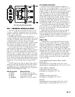
Page 4: ...ght forward to to and shield to shield For unbalanced operation we recommend using two conductor cable with shield The cable is wired to the CP 52 the same as for balanced operation At the other end of the cable connect the wire to signal hot and both the and shield wires to ground important If you use single conductor cable with shield connect the shield gnd wire to both the and shield pins at th...

Page 5: ...he CP 52 Connect each wire to the 5 pin connector by fully inserting it in the correct socket and tightening the screw Make sure wires are free of nicks and that the cable jacket is stripped back sufficiently to allow it to lie in the electrical box with the remote assembly inserted Use the flat head 6 screws supplied with the kit to mount the remote assembly and silk screened front panel to the e...

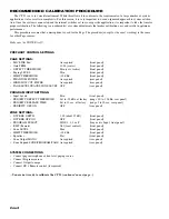
Page 6: ...RESHOLD Min ccw Active front panel Paging LEVEL Min front panel LIMIT THRESHOLD 20 dBu front panel PHANTOM POWER As required rear panel HIGH LOW CUT FILTER As required rear panel PAGE LEVEL TRACKS ZONE LEVEL OFF rear panel PROGRAM INPUT SETTINGS Input Levels Min front panel PRIORITY DETECT THRESHOLD Set to 50 dBu at factory range to 35 dBu rear panel PRIORITY RELEASE TIME Set to 12 sec at factory ...

Page 7: ...e on due to background sound 7 With an active Program source playing speak into the Paging mic Adjust the Paging LEVEL control to provide the correct Page to Program mix If the Paging Detect Threshold is set too high there may be a delay before speech is heard To correct this lower the Paging Detect Threshold setting 8 Set the Paging LIMIT THRESHOLD to limit the maximum Page level to the loudest d...

Reviews: