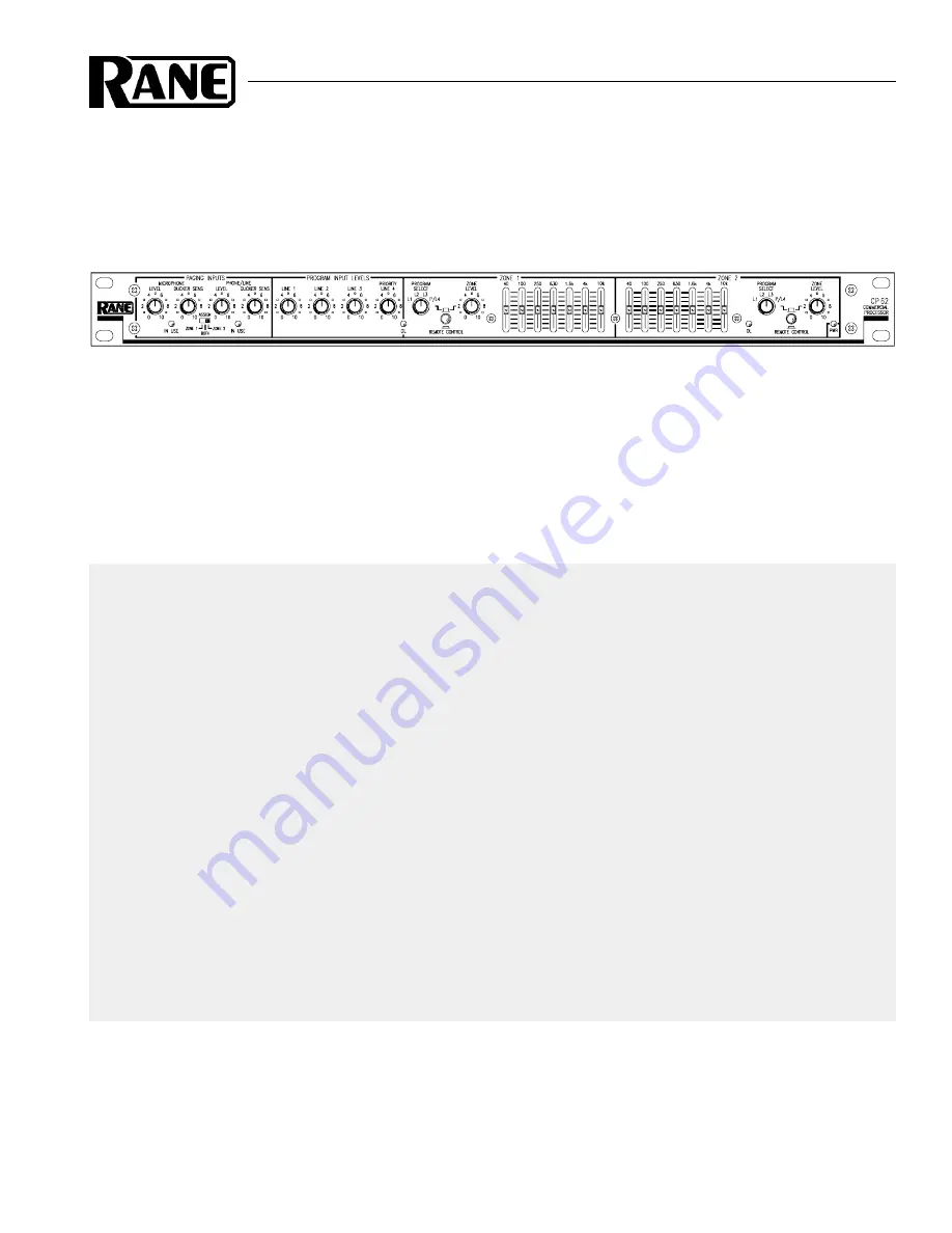
Manual-1
OPERATORS MANUAL
CP 62
COMMERCIAL PROCESSOR
QUICK START
This unit packs a lot of features, so let’s start by just getting some music running through it. Make all connections
with the power amplifiers off. The CP 62 must be earth grounded for safety and correct operation. Connect a wire to the
grounding screw (near the POWER input jack) to a known earth ground. The CP 62 can drive two zones with separate
program and levels. Zone 1 can be a stereo zone (determined by the MONO/STEREO MODE switch on the rear), we’ll
hook that up next. The zone outputs are fully balanced, so we recommend the use of balanced cables (¼" Tip-Ring-
Sleeve) to connect to the amplifier. If the amplifier’s inputs are unbalanced, the CP 62 still works fine using ¼" (Tip-
Sleeve) connectors if cable lengths are kept short (under 10 feet). Connect the CP 62 ZONE 1 LEFT and RIGHT
OUTPUTS to the amplifier inputs. Hook up a CD or tuner to PROGRAM INPUT 1 using a standard stereo RCA cable.
Plug the RS 2 power supply into the red power connector on the back of the CP 62 and its line cord into the AC line—the
PWR LED should come on. Turn both ZONE LEVEL controls fully counter clockwise. Turn the PROGRAM INPUT
LEVEL LINE 1 up to 12 o’clock. Now it’s OK to turn on the amplifer. Slowly turn up ZONE 1 LEVEL. With the CD/
tuner playing, you should hear program coming from the speakers.
Now connect your other sources to the other PROGRAM INPUTS. Select each input with the ZONE 1 PROGRAM
SELECT switch. Adjust individual source levels with the PROGRAM INPUT LEVELS. Adjust zone volume with the
ZONE LEVEL control. Tailor the zone 1 equalizer to your liking. Connect a second amplifer to the ZONE 2 OUTPUT
and run separate programs and levels to another room.
Never connect anything except an Rane RS 2 power supply to the thing that looks like a red telephone jack on
the rear of the CP 62. This is an AC input and requires special attention if you do not have an operational power supply
exactly like the one originally packed with your unit.
Never connect anything except the optional Rane R1 zone assign or R2 source and level remote controls (or
their equivalent) to the things that look like black telephone handset jacks on the rear of the CP 62. These are not
telephone connections.

