background image

Manual-7

Preparing the cables

All modular connectors are not created equal. The typical

modular plug that connects to your telephone is a 6-position/
4-conductor connector, named by an RJ number to describe it
(i.e. RJ11, RJ14). This type of connector will not fit into the
CP 62 remote outlets. The appropriate connector for the CP
62 is a 4-position/4-conductor, and is referred to as a “tele-
phone modular handset connector”. It does not have an RJ
number to describe it. Most companies have their own
different part numbers for this part.
1. Install standard copper stranded 28-26 guage 4 conductor

flat telephone cable to an empty electrical box where the
remote is to be located. Do not use high flexibility tinsel
cable. Strip an end to check if necessary. The ampere
rating for tinsel wire is too low, affecting system remote
reliability. Maximum cable distance from the CP 62 is 200
feet.

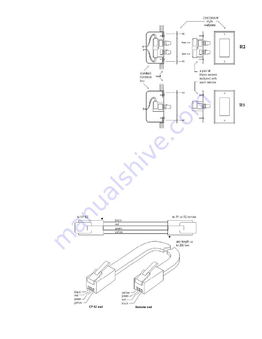
2. Install a modular handset connector on each end of the

telephone cable, taking note of wire colors as shown in
Figure 4. Special crimp hand tools and the connectors may
be purchased at commercial telephone supply outlets. This
tool is different than standard telephone modular line types.

3. Plug one end into the MAIN jack of the remote control

unit. Connect the other end to the desired jack on the back
of the CP 62.

Installation

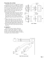
The R1 and R2 remote control units will mount in

standard U.S. electrical boxes in the same way as wall
switches or outlets, as shown in Figure 2. Use a DECORA

®

wall plate or equivalent to allow the labeling on the front of
the remote to be visible. DECORA wall plates are available in
a wide range of colors at most hardware stores.

Figure 2. Installation

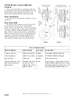
Figure 4. Remote connector wiring

Summary of Contents for CP 62

Page 1: ...of the CP 62 and its line cord into the AC line the PWR LED should come on Turn both ZONE LEVEL controls fully counter clockwise Turn the PROGRAM INPUT LEVEL LINE 1 up to 12 o clock Now it s OK to tu...

Page 2: ...ERNAL JUMPER OPTION described on page Manual 4 6 Front panel ZONE ASSIGN switch Selects which zone the rear panel selected paging input will be routed to and activate program ducking For more informat...

Page 3: ...INSERT jacks These unbalanced Tip Send Ring Return connectors allow insertion of external signal processors such as equalizers or compressor limiters Zone 1 is stereo or dual mono If zone 1 is used a...

Page 4: ...set by daisy chaining two optional R2 remote controls This overrides the front panel level control SOURCE LEVEL REMOTE INPUTS Two 4 pin modular jacks on the rear control source and level remotely usin...

Page 5: ...ich signal is controlled from the front panel PAGING ZONE ASSIGN switch and which is controlled via the rear panel REMOTE ZONE ASSIGN connector Rear Panel balloon 15 is determined by the rear panel PA...

Page 6: ...cable from the MAIN jack of the second R2 into the AUX jack on the first R2 A third R2 plugged into the CP 62 ZONE 2 REMOTE jack gives control over the third mono zone operated as Zone 2 Figure 1a Fi...

Page 7: ...y The ampere rating for tinsel wire is too low affecting system remote reliability Maximum cable distance from the CP 62 is 200 feet 2 Install a modular handset connector on each end of the telephone...

Page 8: ...ed Here are some things to try 1 Try combinations of lifting grounds on units that are supplied with ground lift switches or links 2 Verify that all chassis are tied to a good earth ground i e through...

Reviews: