Manual-
REMOTE MOUNTING
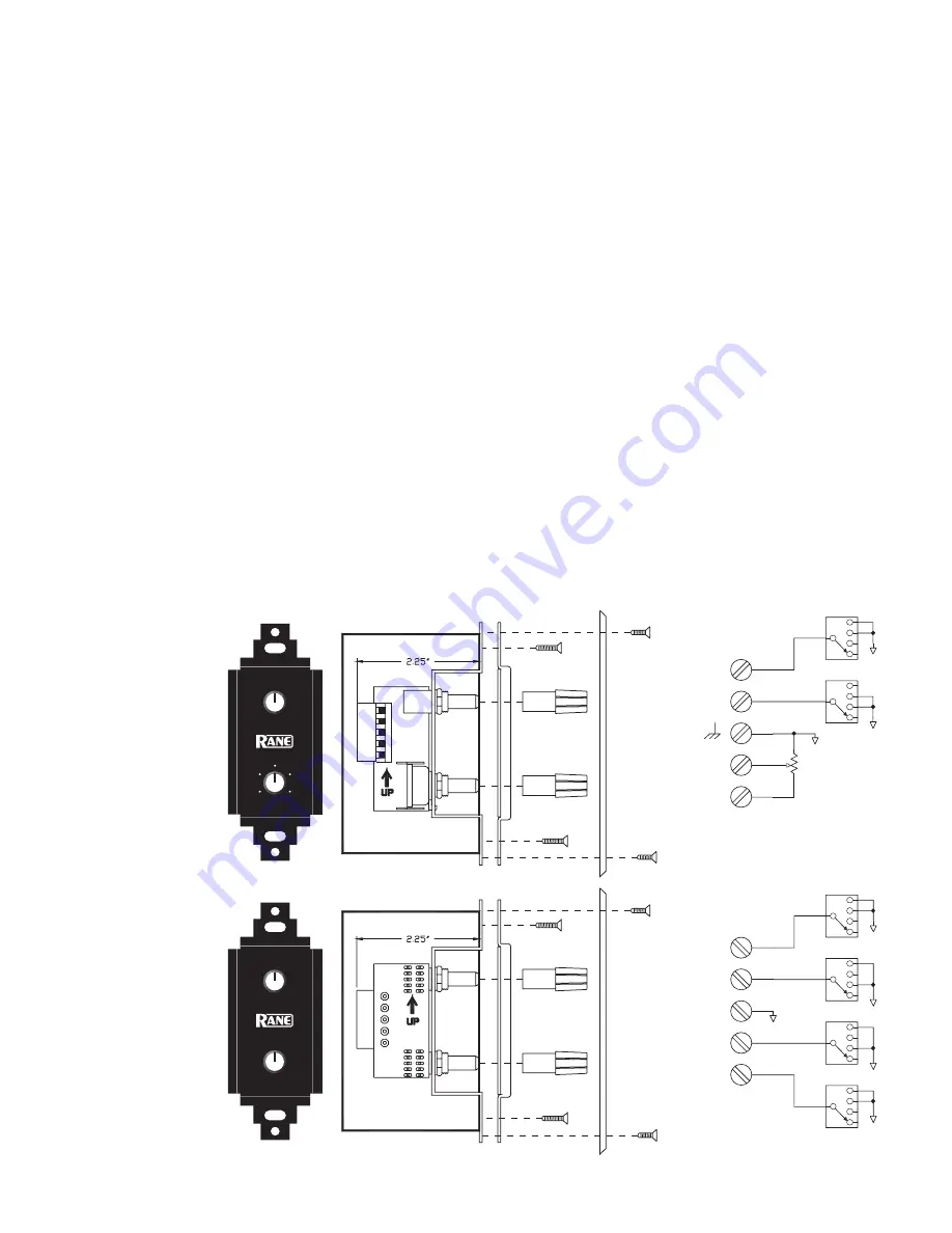
The ZR 1 and PR 2 remote assemblies mount in a standard U.S.
electrical box with a minimum depth of 2.25". Be sure to note
the wire color of each input in order to facilitate correct wiring
to the CP 64S. Connect each wire to the Euro connector by fully
inserting it in the correct socket and tightening the screw. Make
sure wires are free of nicks and that the cable jacket is stripped
back sufficiently to allow it to lie in the electrical box with the
remote assembly inserted. Use the flat head #6 screws supplied
with the kit to mount the remote assembly and silk-screened
front panel to the electrical box (see above diagram). Note the
“UP” arrow screened on the printed circuit board of each remote
(mount it pointing
up
).
The silk-screened front panel metal is painted on both sides.
This allows you to custom silk-screen the panel or add your own
custom decals. Simply install the modified front panel with your
art facing out, and you are in business!
Install each knob so that the line on the knob is properly
aligned with the silk-screening on the front panel of the remote
assembly. Install any Decora plate of your choice. For a secured
installation, you may wish to leave the knobs off and use a blank
Decora plate to cover the remote after adjustment.
PAGE 2 ASSIGN
PAGE 1 ASSIGN
BOTH
OFF
BOTH
Z1
OFF
Z2
Z1 Z2
PROGRAM SELECT
LEVEL
8
2
10
0
4
6
L1
L3
L2
P
D
ec
or
a
pl
at
e
(n
ot
in
cl
ud
ed
)
D
ecora plate (not included
)
ZR 1
Zone / Volume
PR 2
Paging Assign / Volume
1
2
3
4
5
S2A
6
7
8
9
10
S2B
2
3
4
1
5
J1A
5 POS TERM
GND
GND
6
7
8
9
10
S1B
1
2
3
4
5
S1A
GND
GND
GND
Z2
Z1
GND
Z1
Z2
PAGE 1
PAGE 2
PAGE REMOTE (PR 2)
1
2
3
4
5
S1A
6
7
8
9
10
S1B
2
3
4
1
5
J1A
5 POS TERM
GND
GND
GND
D1
D0
Vc
Vr
ZONE REMOTE (ZR 1)
C
W
2
1
3
R1
2KRD
WIRE TYPES
Variations in wire type do not greatly affect the performance of
the remote controls. 22-gauge stranded wire with a flexible jacket
is recommended. You may use 5-conductor unshielded remote
control signal cable for shorter runs (less than 200 feet [60
meters]), or 4-conductor (2 pair) shielded remote control signal
cable (use the shield as the ground return) for longer runs (200
to 1000 feet [60 to 300 meters]). The type of wire required is
influenced by your installation and local electrical codes.
Rane Corporation does
not
provide or source cable. Please
contact your local retail or wholesale outlet,
not
the factory. The
following is a short list of suitable cable types:
CONSOLIDATED ELECTRONIC WIRE AND CABLE
Plenum cable:
Unshielded remote control signal cable CAT. # 9896
Shielded remote control signal cable CAT. #9877, CAT. #9852
WEICO WIRE & CABLE INC.
Communication and control cable:
Multiconductor, unshielded CAT. #7606
ALPHA
Communication and control cable:
Multiconductor, unshielded CAT. #1175C
BELDEN
Unshielded remote control signal cable CAT. # 88741
Shielded remote control signal cable CAT. # 88723


