CP66
Installation Manual
10
Hardware Connections
Program Inputs
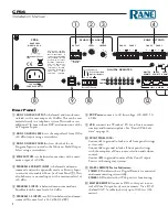
Connect each Input’s audio source to one of the RCA in-
puts for Program 1-4, or the balanced Euro inputs for Pro-
grams 5 & 6. If you have a high priority input, such as a
jukebox or notification system, connect this to Program 6.
It is a good idea to make a note of which input is connected
to each Program for creating labels in the CP66 Software.
Page Inputs
If your system uses an analog Paging input, connect the
microphone or line-level source to the balanced
Page 1
inPut
. Select the appropriate switch setting for
line
,
Mic
,
or
Mic +24v
with Phantom Power. Connect a push-to-talk
switch, if available, to the
Page 1 en
input. This switch is
active low and will engage while the switch is closed and
continue paging until released.
The DIP switch on the rear panel labeled
ZOne aSSign
selects which Zones are paged when
Page 1 engage
is
active.
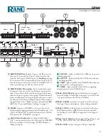
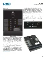
If your system uses the PAGER2 paging station, simply
plug the CAT 5 cable into the port marked
Pager2
. All
status indicators for PAGER2 light green when powered. If
one or more is not lit or is intermittent, check the cabling.
Zone Outputs
Each of the Six Zone Outputs drives a balanced Euro con-
nector up to +20 dBu. Connect these to the amplifiers for
each associated Zone. It is a good idea to note which Zone
is which, for source selection and naming later.
Remotes and Linking
All Remote devices with the CP66 use shielded CAT 5e
cable (or better) with RJ-45 connectors at both ends. Refer
to the descriptions on pages 5 and 8. If you are linking
remotes, see"Zone and Remote Linking" on page 12.
Shielding and Grounding
If you hear a hum or buzz in your system from an input
or zone output, you may have a shielding or grounding
problem. Unbalanced connections as found in RCA termi-
nals should be no longer than 10 feet (3 meters). Consult
the "Sound System Interconnection" RaneNote for help at
http://rane.com/note110.html
.
Setup Procedure
Set the system in the following order to ensure an optimal
setup for dynamic range and noise characteristics.
Note: To restore the unit to its factory settings, hold both
the
left and right
cursor buttons while powering
the unit.
• Connect the
ZOne OutPutS
to amplifiers.
• Connect all
PrOgraM inPutS
.
• Connect the analog
Page 1 inPut
.
• Connect a PAGER2 (if used) to the
Pager2
port.
• Connect all DR1s or DR3s (if used) to
reMOte ZOne
1-6
ports.
• Connect a DR3 Master Remote (if used) to the
MaSter
reMOte
port.
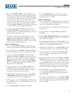
1. Connect the power cord and verify the CP66 powers on.
2. With program sources active, adjust the output volume
on each connected source until it is at the loudest pos-
sible without triggering the “Overload” indicator on the
CP66 front panel. (For an MP3 player this will be full
volume rock ‘n roll, for a TV it will be during commer-
cials with the volume up). Make adjustments with the
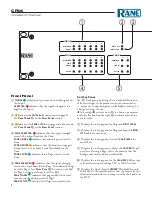
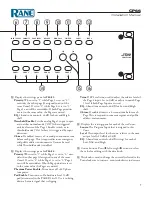
inPut
level
(Front Panel
6
).
3. Set the
Zone Output Level
for Zone 1 (or the zone you
are currently listening to) to minimum (Front Panel
r
).
4. Set the
Source
for this Zone to Program 1.
5. Slowly turn up the
Zone Output Level
for this Zone
until it is at a reasonable volume.
6. Set the
Source
for this Zone to Program 2.
7. Adjust the
Input Level
for Program 2 so it is as close as
possible to Program 1. The goal is to have no change in
volume when switching between different sources.
8. Select each of the remaining sources individually and
set their
Input Levels
to match all other
Input Levels
as closely as possible. If one isn’t loud enough to match,
turn down the others accordingly.
9. Now that your Inputs are leveled, set the
Zone Output
Level
and
Zone EQ
settings for each of the six Zones.
Set
Zone Output Level
as close to 0 dB as your ampli-
fier allows.


