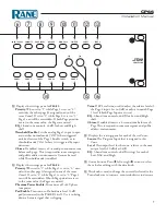
CP66
Installation Manual
8
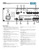
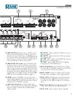
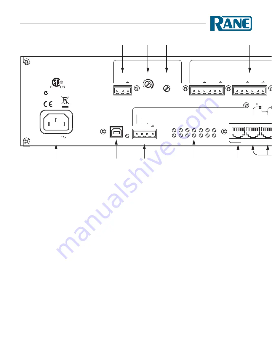
Rear Panel
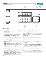
1
MuSic On HOld OutPut
:
is balanced and transformer
isolated, with a max output of +20 dBu. This can be con-
nected directly to a telephone system. This works as an
additional 7th zone without DSP, and mirrors one of the
six Program Inputs.
2
MuSic On HOld level
:
sets the output level from Off to
+20 dBu. Adjust using a screwdriver.
3
MuSic On HOld SOurce
:
selects which of the six
Program Inputs is routed to the Music on Hold Output.
Select using a screwdriver.
4
ZOne OutPutS
:
are balanced connections with a maxi-
mum output of +20 dBu.
5
PrOgraM 6 PriOrity inPut
:
is balanced and mono-
summed, and can be optionally used as a Priority Input
to override into enabled Zones (see Front Panel
7
). This
also behaves as a normal input, with a maximum level of
+20 dBu.
6
PrOgraM 5 inPut
:
is balanced mono-summed on a
Euroblock with a max level of +20 dBu.
7
PrOgraM 1-4 inPutS
:
are RCA unbalanced and mono-
summed. The max level is 14.3 dBu (12 dBV).
8
IEC Power:
connects to AC line voltage, 100-240V, 50-
60 Hz.
9
uSB
: connects to a Windows ® PC for software commu-
nication and firmware updates. See "Rane CP66 Soft-
ware" on page 14.
0
FrOnt Panel lOck
:
Connect
l1
to ground to lock out all front panel settings
as view-only.
Connect
l2
to ground to lock all front panel settings
with the exception of Zone source selection and volume
control.
Connect
M1
to ground to mute all the Zone Outputs.
For use with emergency systems.
q
digital reMOte
Status Indicators:
cOMM
LED indicates that a Digital Remote is connected
and communicating successfully.
POwer
LED indicates the CP66 power is functioning.
w
MaSter reMOte:
Connect a DR3 to this port to con-
trol all Zone Output Levels on one remote. Use a RJ-45
shielded CAT 5e cable (or better) up to 1000 feet (304
meters).
2
1
RANE CORP.
MADE IN U.S.A.
+ −
M1
M
POWER
COMM
L2
L1
CP66
PAGE 1
PAGE 2
R
L
4
5
6
PRIORITY INPUT
3
MUSIC ON HOLD
USB
Front Panel Lock
LEVEL
OUTPUT
Transformer
Isolated
+ −
ZONE 6
+ −
ZONE 5
+ −
ZONE 4
+ −
ZONE 3
+ −
ZONE 2
+ −
ZONE 1
+ −
RIGHT
+ −
LEFT
+ −
RIGHT
+ −
+
P1
ZONE
ASSIGN
−
LEFT
100-240 V
50/60 Hz 20 WATTS
LINE
MIC+24V
MIC
INPUT
ENABLE
AUDIO RX
AUDIO TX
COMM
POWER
LINK
LINK
LINK
LINK
LINK
MASTER
REMOTE
ZONE 6
REMOTE
ZONE 5
REMOTE
ZONE 4
REMOTE
ZONE 3
REMOTE
ZONE 2
REMOTE
ZONE 1
REMOTE
PAGER
2
DIGITAL REMOTES
ZONE OUTPUTS
PROGRAM
INPUTS
LEVEL
SOURCE
1
6
2
5
3
4
ACN 001 345 482
This device complies
with Part 15 of the FCC
Rules. Operation is
subject to the following
two conditions: (1) this
device may not cause
harmful interference,
and (2) this device
must accept any
interference received,
including interference
that may cause
undesired operation.
Z6 Z5 Z4 Z3 Z2 Z1
FP Zone Control Only
Mute All Outputs
Ground To Enable
Ground To Enable
CLASS 2 WIRING SHIELDED CAT5e 24 VDC @ 50 mA
100 mA
1 2 3 4 5 6
2 3
4
5
6
7
1
8
9
0
q
w
t
r
u
y
i o p a
e


