
Manual-1
DC 24
DYNAMIC CONTROLLER
OPERATORS MANUAL
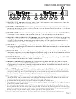
DC 24 CONNECTION
Placing the DC 24 within the chain of events in your system
varies slightly depending on application. If you are assembling
a sound reinforcement system, the DC 24 would typically be
placed between the equalizer (you do use one, don’t you?) and
the active crossover, or the power amplifier if passive crossovers
(or the DC 24 crossover) are used.
In recording applications, the DC 24 may be used in con-
junction with insert loops on the mixing console or in series
with the outputs en route to the recorder. Most consoles allow
headphone monitoring of the processed signal if the device is
connected to the inserts. A most useful feature. If the DC 24 is
used on mixdown, it may be connected to the output of the mul-
tichannel recorder or again on inserts of the mixdown console.
Many recording situations require that the DC 24 be con-
nected to the patch bay in the system so it may be easily moved
from one signal location to another. This call should be made
based upon the requirements of the application.
Wiring of this and all components should follow the Sound
System Interconnection RaneNote included in this manual. This
note details standard wiring conventions which should be used
to prevent noise and distortion. Also see the Chassis ground
point on page Manual-3.
QUICK START
Shredded, this document makes excellent packing material. In its present form, it makes interesting and useful reading. If you
run out of patience quickly, at least read this part to make sure you don’t exterminate everything in a two mile radius by doing some-
thing wrong.
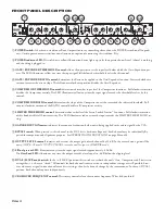
In a nutshell, to use the DC 24 as a conventional dual channel compressor/limiter, ensure that the
CROSSOVER ENGAGE
switch on the rear is in its
out
position. Attach one or two channels of inputs and outputs to the respective connectors on the rear.
With all
RATIOS
down
,
LIMITER THRESHOLD
all the way
up
and the
LEVEL
controls in
center-detent
you have an expensive
patch cord. Make sure the
BYPASS
switches are
out
and set the
GATE
and
COMPRESSOR
for the desired ratios and thresholds.
Turning the
LIMITER THRESHOLD
down decreases the level at which limiting occurs. The
GATES
and
COMPRESSORS
may
both be activated by the source material applied to Channel 1 if the
DUAL/SLAVE
switch is pressed
in
. This is a normal condition
for true stereo program material.
To use the DC 24 's crossover bandsplit mode, be sure the rear panel
CROSSOVER ENGAGE
switch is
in
. Connect the input to
CH 1/CROSSOVER IN
. With the rear panel
OUTPUTS
switch set to
SEPARATE
, split outputs are available at the
CH 1/LOW
OUT
and
CH 2/HIGH/COMBINE OUT
jacks. With the
OUTPUTS
switch at
COMBINE
, use only the
CH 2/HIGH/COM-
BINE OUT
jack for a mono sum of high and low channels.
NEVER CONNECT ANYTHING EXCEPT AN RS 1 OR OTHER APPROVED RANE AC POWER SUPPLY TO THE
THING THAT LOOKS LIKE A TELEPHONE JACK ON THE REAR OF THE DC 24.
This is an AC input and requires some
special attention if you do not have an operational power supply
EXACTLY
like the one that was originally packed with your unit.
WEAR PARTS:
This product contains no wear parts.
DC 24
THRESHOLD
THRESHOLD
RATIO
THRESHOLD
RATIO
SIG LEVEL OL
BYPASS
MODE
FREQUENCY
POWER
COMPRESSOR
CH 1 OUTPUT
LIMITER
CROSSOVER
GAIN
REDUCTION
THRESHOLD
THRESHOLD
RATIO
THRESHOLD
RATIO
SIG LEVEL OL
BYPASS
GATE / EXPANDER
GATE / EXPANDER
COMPRESSOR
CH 2 OUTPUT
LIMITER
GAIN
REDUCTION
LOW
(:1)
(:1)
SLAVE
DUAL
DYNAMIC
CONTROLLER
-50
10
-40
2
-30
-20
3
-10
1
10
1
10
8
6
4
7
5
1.1
4
1.2
1.4 1.6 2
3
-6
24
12
+6
0
6
3
-40
-30
-20
10
0
+12
-12
+6
-6
0
HIGH
(:1)
(:1)
24
12
6
3
0
7k
200
70
100
75
90
150
125
400
2k
800
1.2k
+20
-20
-6
+6
0
+20
-20
-6
+6
0
+12
-12
-10
20
-48
2
3
1
10
8
6
4
7
5
-50
10
-40
-30
-20
0
-10
(:1)
1
10
1.1
4
1.2
1.4 1.6 2
3
-40
-30
-20
0
10
-10
20
-48
6k
4k
0
0


