Manual-3
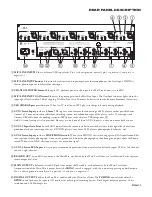
REAR PANEL DESCRIPTION
1
MIC/LINE INPUTS 1-6
are balanced XLR input jacks. Pin 1 is chassis ground (neutral), pin 2 is positive (+), and pin 3 is
negative (-).
2
MIC/LINE INPUT buttons 1-6
switch the sensitivity and input impedance for microphone or line-level input. If LINE is
chosen, phantom power is defeated for that input.
3
PHANTOM POWER buttons 1-6
apply 12V phantom power to the input if the Mic/Line button is set to MIC.
4
MIC/LINE INPUT GAIN trims 1-6
adjust the preamp gain for the Mic/Line Input. The OverLoad indicator lights when the
input signal level is within 5 dB of clipping. The Mic/Line Gain Trim may be decreased to provide more headroom if necessary.
5
USB CHARGE port
provides up to 500 mA at 5V to allow an MP3 player to charge its battery during playback.
6
AUX 1 Stereo Input
provides a
3.5 mm
TRS input as a convenience for connecting an MP3 player or other portable device.
Connect a 3.5 mm stereo audio cable from a docking station, or headphone output of the player, to this 3.5mm input jack.
Connect USB cable from the docking station or MP3 player to the adjacent USB charge port
5
.
An RCA stereo line input is also provided. However, use only one of these AUX 1 Inputs at a time, do not use both at once.
7
AUX 1-5 Input Gain Trim
on each AUX input allows the system installer to match the relative input signal levels of various
professional and consumer input devices (CD/DVD players, tape decks, MP3 players, phonographs, keyboards, etc).
8
AUX 4 Stereo Input
provides a
LINE/PHONO switch
. When set to PHONO, this switch engages an RIAA equalization filter
to accept input from a phonograph. Connect the ground cable from the phonograph to the phono ground post above the Phono
switch. When set to LINE, this input accepts any stereo line signal.
9
AUX 1-5 Stereo RCA Inputs
in stereo pairs accommodate professional consumer-level unbalanced inputs. White = left channel,
and red = right channel.
0
RECORD OUT
stereo RCA jack outputs the Main Mix, unaffected by the Main Level fader, at a level dictated by the adjacent
record output level trim.
q
MAIN OUTPUT
is balanced stereo XLR jacks that output the Main Mix, with volume set by the Main Level fader.
A mono version of the Main Mix is output here if the
MONO
switch is engaged, with the same mix appearing on both outputs.
Pin 1 is chassis ground (neutral), pin 2 is positive (+), and pin 3 is negative (-).
w
DIGITAL OUTPUTS
deliver the Main Mix, unaffected by the Main Level fader. The
TOSLINK
optical jack and/or the
S/PDIF
coaxial jack may be input to CD recorders or other digital recording devices. Both digital outputs operate at 24-bit
resolution and 48 kHz sample rate.
ACN 001 345 482
S/PDIF
RIGHT
LEFT
MONO
TOSLINK
USB AUDIO
IN / OUT
MADE IN U.S.A.
RANE CORP.
MLM 65
PIN 2: POSITIVE
PIN 3: NEGATIVE
PIN 1: CHASSIS GND
CLASS 2 WIRING
100-240 V
50/60 Hz 15 WATTS
This device complies with Part 15 of the FCC Rules. Operation is
subject to the following two conditions: (1) this device may not cause
harmful interference, and (2) this device must accept any interference
received, including interference that may cause undesired operation.
–12 0
–12
0
0
+12
–12 +12
0
–12 +12
0
–12 +12
0
–12 +12
PHANTOM
POWER
MIC
GAIN
LINE
12V
OL
GAIN
OL
GAIN
OL
GAIN
OL
GAIN
OL
GAIN
OL
PHANTOM
POWER
12V
PHANTOM
POWER
12V
PHANTOM
POWER
12V
PHANTOM
POWER
12V
PHANTOM
POWER
12V
MIC
LINE
MIC
LINE
MIC
LINE
MIC
LINE
LINE
PHONO
MIC
LINE
MAIN OUTPUT
RECORD OUT
AUX 5 IN
AUX 4 IN
AUX 3 IN
AUX 2 IN
AUX 1 IN
USB CHARGE ONL
Y
5 VDC @ 500 mA
DIGITAL OUTPUTS
MIC 6
MIC 5
MIC 4
MIC 3
MIC 2
MIC 1
WARNING
To reduce the risk of fire or electrical shock do not expose this
equipment to rain or moisture. Do not remove cover. No user
serviceable parts inside. Refer servicing to qualified personnel.
AVIS
Risque de choc electique — Ne pas ouvrir
1
2
3
4
5
6
8
9
7
0
q
e
r
w

