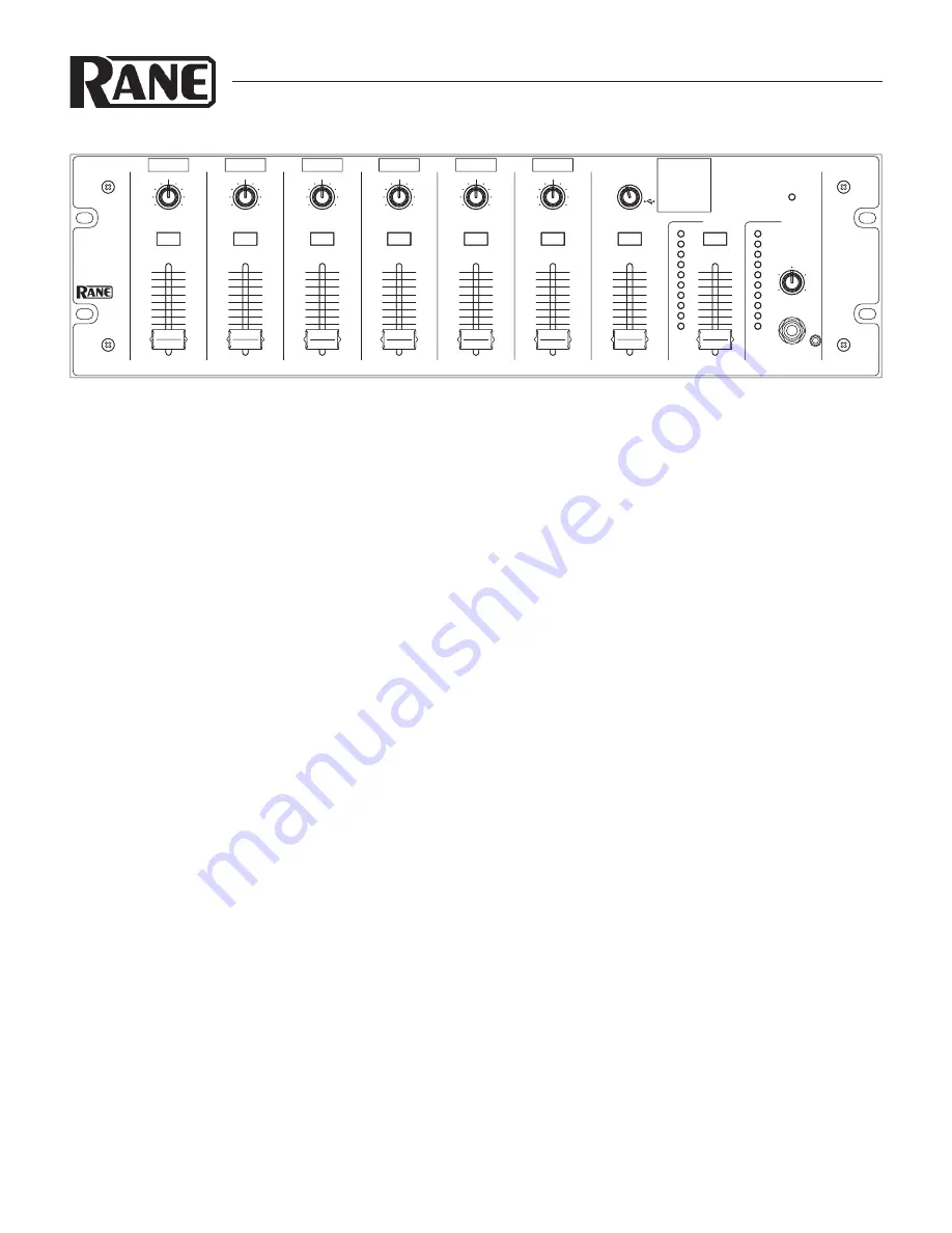
background image

Manual-1

MLM65

MIC & LINE MIXER

OPERATORS MANUAL

WEAR PARTS:

 This product contains no wear parts.

QUICK START

Are you being pursued by a slow-moving, yet tenacious, gang of 

zombies? Do you need to get your new MLM65 installed before 

they overwhelm you and eat your brain? Well, we at Rane are 

here to help! Use this Quick Start to get the most out of your 

MLM65 in the least amount of time.

Mic Inputs 1 through 6 may be microphone or line-level. The 

choice between the two is made by pushing in the Input’s Line 

button on the rear panel.

Push the Phantom Power (when needed) for each Mic Input.

While speaking/singing/shouting loudly into the micro-

phone, use a screwdriver to adjust the Gain pot until the OL 

LED illuminates only during extreme peaks.

Push in the Aux 4 phono/line switch if you are connecting a 

phonograph.

With the Stereo Cue button selected, match the input levels 

of Aux 1 through 5 by playing typical program material into 

each Aux input, selecting that input using the Stereo Selector, 

and adjusting the Aux input level with a screwdriver until the 

peaks on the Cue Meter hover around 0 to +7 dB.

With an audio mix playing at a loud level +7 dB to OL on 

the Main Meter, adjust the Record Out level until the meter on 

your recording device gets close to maximum without overload-

ing.

If you are installing the MLM65 with input sources that 

don't change, Rane has an easy PDF template to fill out, print, 

cut, and place labels above each input. Download this at the 

MLM65 web page at www.rane.com/mlm65.html.

Look out behind you! Scissors are ineffective on zombies.

10

0

2

4

8

6

OL

+7

+4

+2

0

-4

-2

-7

-10

-20

OL

+7

+4

+2

0

-4

-2

-7

-10

-20

0

1

2

3

4

5

6

7

8

9

10

0

1

2

3

4

5

6

7

8

10

9

0

1

2

3

4

5

6

7

8

9

10

0

1

2

3

4

5

6

7

8

10

9

0

1

2

3

4

5

6

7

8

9

10

0

1

2

3

4

5

6

7

8

10

9

0

1

2

3

4

5

6

7

8

9

10

0

1

2

3

4

5

6

7

8

10

9

0

1

2

3

4

5

6

7

8

9

10

0

1

2

3

4

5

6

7

8

10

9

0

1

2

3

4

5

6

7

8

9

10

0

1

2

3

4

5

6

7

8

10

9

0

1

2

3

4

5

6

7

8

9

10

0

1

2

3

4

5

6

7

8

10

9

0

1

2

3

4

5

6

7

8

9

10

0

1

2

3

4

5

6

7

8

10

9

LEVEL

MLM 65

MIC / LINE MIXER

PAN

MIC 2

R

L

CUE

LEVEL

PAN

MIC 1

R

L

CUE

LEVEL

PAN

MIC 3

R

L

CUE

LEVEL

PAN

MIC 4

R

L

CUE

LEVEL

PAN

MIC 5

R

L

CUE

LEVEL

LEVEL

PAN

MIC 6

STEREO

R

L

CUE

LEVEL

POWER

CUE

CUE

AUX

SOURCE

MAIN

CUE

PHONES LEVEL

2

5

USB

1

3 4

CONNECTION

When connecting the MLM65 to other components in your 

system for the first time, leave the power cord for last. This gives 

you a chance to make mistakes and correct them without dam-

age to your fragile speakers, ears and nerves.

MIC INPUTS

The six XLR jacks provided on the MLM65 are balanced MIC/

LINE inputs. They also accept unbalanced connections. Use 

only shielded cable for inputs. For best noise rejection use two-

conductor-plus-shielded wire, even for unbalanced operation. 

Connect the shield at both ends to help insure proper grounding. 

See the Sound System Interconnection RaneNote for all cable 

adaptations. Rane follows the AES recommended practice of 

pin 2 positive, pin 3 negative, and pin 1 to shield. Switch any 

input connected to a microphone to the MIC position (out) us-

ing the associated switches on the rear panel. When connecting 

line-level signals, switch the input to the LINE position (in). A 

phantom power switch is provided for each MIC input. If LINE 

is selected, Phantom Power is disabled for that input.

AUX INPUTS

The five Aux Inputs are line-level unbalanced inputs on stereo 

RCA connectors. AUX 1 includes a 3.5 mm stereo TRS jack. 

Only connect to one AUX 1 input (RCA or TRS) at a time. 

When using AUX 4 as a phono input, connect the phonograph 

ground wire to the phono ground post above the AUX 4 input.

MAIN OUTPUT

The MLM65’s Main Outputs are balanced, XLR Outputs. The 

same wiring conventions as the XLR Inputs apply. For unbal-

anced Output connections do not tie pin 3 (i.e., “–”) to ground. 

If the Main Output is connected to a mono loudspeaker system, 

use either the left or right Main output jack and push in the 

MONO switch.

continued on page Manual-4...

Summary of Contents for MLM 65

Page 1: ...4 5 6 7 8 10 9 0 1 2 3 4 5 6 7 8 9 10 0 1 2 3 4 5 6 7 8 10 9 0 1 2 3 4 5 6 7 8 9 10 0 1 2 3 4 5 6 7 8 10 9 0 1 2 3 4 5 6 7 8 9 10 0 1 2 3 4 5 6 7 8 10 9 LEVEL MLM 65 MIC LINE MIXER PAN MIC 2 R L CUE LEVEL PAN MIC 1 R L CUE LEVEL PAN MIC 3 R L CUE LEVEL PAN MIC 4 R L CUE LEVEL PAN MIC 5 R L CUE LEVEL LEVEL PAN MIC 6 STEREO R L CUE LEVEL POWER CUE CUE AUX SOURCE MAIN CUE PHONES LEVEL 2 5 USB 1 3 4 D...

Page 2: ...ain readily operable To completely disconnect this apparatus from the AC mains disconnect the power supply cord plug from the AC receptacle 16 This apparatus shall be connected to a mains socket outlet with a protective earthing connection 17 When permanently connected an all pole mains switch with a contact separation of at least 3 mm in each pole shall be incorporated in the electrical installat...

Page 3: ...ible Pour déconnecter totalement l appareil du secteur débranchez le câble d alimentation de la prise secteur 16 Cet appareil doit être branché à une prise terre avec protection 17 Quand il est branché de manière permanente un disjoncteur tripolaire normalisé doit être incorporé dans l installation électrique de l immeuble 18 En cas de montage en rack laissez un espace suffisant pour la ventilatio...

Page 4: ...0 1 2 3 4 5 6 7 8 9 10 0 1 2 3 4 5 6 7 8 10 9 0 1 2 3 4 5 6 7 8 9 10 0 1 2 3 4 5 6 7 8 10 9 0 1 2 3 4 5 6 7 8 9 10 0 1 2 3 4 5 6 7 8 10 9 LEVEL MLM 65 MIC LINE MIXER PAN MIC 2 R L CUE LEVEL PAN MIC 1 R L CUE LEVEL PAN MIC 3 R L CUE LEVEL PAN MIC 4 R L CUE LEVEL PAN MIC 5 R L CUE LEVEL LEVEL PAN MIC 6 STEREO R L CUE LEVEL POWER CUE CUE AUX SOURCE MAIN CUE PHONES LEVEL 2 5 USB 1 3 4 CONNECTION When ...

Page 5: ...in Level fader the rear panel Record Out gain control and the TOSLINK S PDIF and USB digital outputs The Main Level fader has no effect on this display The 0 dB LED corresponds to a level of 20 dBFS 20 dB before clipping 9 CUE PHONES LEVEL control sets the volume of the input selected with the lit Cue button to the stereo headphone outputs 0 CUE meter displays the signal level of the input selecte...

Page 6: ...s in stereo pairs accommodate professional consumer level unbalanced inputs White left channel and red right channel 0 RECORD OUT stereo RCA jack outputs the Main Mix unaffected by the Main Level fader at a level dictated by the adjacent record output level trim q MAIN OUTPUT is balanced stereo XLR jacks that output the Main Mix with volume set by the Main Level fader A mono version of the Main Mi...

Page 7: ...e Main meter displays the peak level of the mix pre Main fader A mix with optimal dynamic range normally lights the meter from 0 to 7 dB and only lights the red OL led during the most extreme peaks A peak indication 0 dB on the meter corresponds to 20 dBFS in the mix 20 dB below clipping The stereo Main Mix is sent to the Record Outputs Digital Outputs and the Main Level fader CONNECTION continued...

Page 8: ...layback and recording 16 bit 48 kHz The MLM 65 uses the drivers that ship with Windows and Macin tosh operating systems Once the operating system recognizes the MLM65 the blue LED on the MLM65 rear panel illumi nates WINDOWS OPERATION When Windows detects the MLM65 it automatically sets it as the default Recording and Playback device With Windows XP and Vista any audio applications currently runni...

Page 9: ...X detects the MLM65 it adds it to the list of audio input and output devices but does not automatically set it as the default device Some Macintosh applications allow you to select the device you want to use Other applications only use the device specified as the OSX default We recommend that you set the default audio input and output device to the MLM65 before starting the application you want to...

Page 10: ...ent is modified without writ ten consent of the manufacturer This declaration of conformity is issued under the sole responsibility of Rane Corporation Type of Equipment Professional Audio Signal Processing Brand Rane Model MLM 65 Immunity Results THD N 4 dBu 400 Hz BW 20 Hz 20 kHz Test Description Measurement Conditions RF Electromagnetic Fields Immunity 80 MHz 1000 MHz 1 kHz AM 80 depth 3V m 80 ...

Reviews: