background image

Manual-2

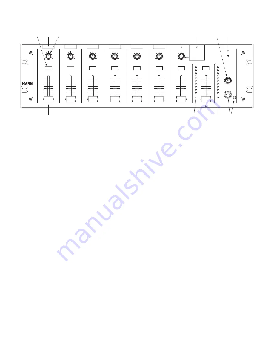
FRONT PANEL DESCRIPTION 

1

 Input LEVEL faders

 are 45 mm sliders that set the volume of each mic or line Input.

2

 CUE buttons 

select one of the Inputs, the Stereo Aux, or the Main Mix to be heard in headphones, and displayed on the Cue 

meter. The button lights yellow when active. The Cue signal is before the Level fader, allowing the user to hear a source in the 

headphones before bringing it into the Main Mix. Only one Cue source is heard at a time.

3

 Input label slots 1-6

 allow you to print your own label for each connected Input, and slip it behind the window. A PDF template 

is downloadable from www.rane.com on the MLM65 page. Cut each label to 1" x .375" [⅜"] (2.5 x .9 cm).

4

 PAN controls 1-6 

send the input audio to both left and right Main Mix channels when in the center (at 12 o'clock). The signal 

moves to the left channel when turned counter-clockwise, and to the right channel when turned clockwise.

5

 STEREO SOURCE

 selects the signal for the Aux Input. Choose from AUX 1, 2, 3, 4, 5 or USB playback from a computer.

6

 Stereo Input Label Slot

 allows you to print a list of input labels and slip it behind the window. A PDF template is downloadable 

from www.rane.com on the MLM65 page. Cut the label to 1.25" x 1.25" [1-¼"] (3.2 x 3.2 cm).

7

 MAIN LEVEL


fader

 is a 45 mm slider that sets the Main Mix volume at the Main Outputs.

8

 Main Mix meter

 displays the sum of all Inputs sent to the Main Mix. This audio level is sent to the Main Level fader, the rear 

panel Record Out gain control, and the TOSLINK, S/PDIF, and USB digital outputs. The Main Level fader has no effect on this 

display. The 0 dB LED corresponds to a level of -20 dBFS (20 dB before clipping).

9

 CUE: PHONES LEVEL


control

 sets the volume of the input selected with the lit Cue button to the stereo headphone outputs.

0

 CUE: meter

 displays the signal level of the input selected with the lit Cue button. The Phones Level control has no effect on this 

display. The 0 dB LED corresponds to a level of -20 dBFS. The Cue meter is also a convenient way to match input levels. Drive all 

inputs with representative input signals, Cue each input individually, and adjust the rear panel input gain trim of each Cued Input 

until the Cue meter indicates 0 dB rms.

q

 CUE: headphone outputs

 accept both 1/4" and 3.5 mm stereo headphone plugs.

w

 POWER indicator 

lights whenever adequate power is applied to the unit.

10

0

2

4

8

6

OL

+7

+4

+2

0

-4

-2

-7

-10

-20

OL

+7

+4

+2

0

-4

-2

-7

-10

-20

0

1

2

3

4

5

6

7

8

9

10

0

1

2

3

4

5

6

7

8

10

9

0

1

2

3

4

5

6

7

8

9

10

0

1

2

3

4

5

6

7

8

10

9

0

1

2

3

4

5

6

7

8

9

10

0

1

2

3

4

5

6

7

8

10

9

0

1

2

3

4

5

6

7

8

9

10

0

1

2

3

4

5

6

7

8

10

9

0

1

2

3

4

5

6

7

8

9

10

0

1

2

3

4

5

6

7

8

10

9

0

1

2

3

4

5

6

7

8

9

10

0

1

2

3

4

5

6

7

8

10

9

0

1

2

3

4

5

6

7

8

9

10

0

1

2

3

4

5

6

7

8

10

9

0

1

2

3

4

5

6

7

8

9

10

0

1

2

3

4

5

6

7

8

10

9

LEVEL

MLM 65

MIC / LINE MIXER

PAN

MIC 2

R

L

CUE

LEVEL

PAN

MIC 1

R

L

CUE

LEVEL

PAN

MIC 3

R

L

CUE

LEVEL

PAN

MIC 4

R

L

CUE

LEVEL

PAN

MIC 5

R

L

CUE

LEVEL

LEVEL

PAN

MIC 6

STEREO

R

L

CUE

LEVEL

POWER

CUE

CUE

AUX

SOURCE

MAIN

CUE

PHONES LEVEL

2

5

USB

1

3 4

2 3

1

4

5 6

w

9

7

8

0 q

Summary of Contents for MLM 65

Page 1: ...4 5 6 7 8 10 9 0 1 2 3 4 5 6 7 8 9 10 0 1 2 3 4 5 6 7 8 10 9 0 1 2 3 4 5 6 7 8 9 10 0 1 2 3 4 5 6 7 8 10 9 0 1 2 3 4 5 6 7 8 9 10 0 1 2 3 4 5 6 7 8 10 9 LEVEL MLM 65 MIC LINE MIXER PAN MIC 2 R L CUE LEVEL PAN MIC 1 R L CUE LEVEL PAN MIC 3 R L CUE LEVEL PAN MIC 4 R L CUE LEVEL PAN MIC 5 R L CUE LEVEL LEVEL PAN MIC 6 STEREO R L CUE LEVEL POWER CUE CUE AUX SOURCE MAIN CUE PHONES LEVEL 2 5 USB 1 3 4 D...

Page 2: ...ain readily operable To completely disconnect this apparatus from the AC mains disconnect the power supply cord plug from the AC receptacle 16 This apparatus shall be connected to a mains socket outlet with a protective earthing connection 17 When permanently connected an all pole mains switch with a contact separation of at least 3 mm in each pole shall be incorporated in the electrical installat...

Page 3: ...ible Pour déconnecter totalement l appareil du secteur débranchez le câble d alimentation de la prise secteur 16 Cet appareil doit être branché à une prise terre avec protection 17 Quand il est branché de manière permanente un disjoncteur tripolaire normalisé doit être incorporé dans l installation électrique de l immeuble 18 En cas de montage en rack laissez un espace suffisant pour la ventilatio...

Page 4: ...0 1 2 3 4 5 6 7 8 9 10 0 1 2 3 4 5 6 7 8 10 9 0 1 2 3 4 5 6 7 8 9 10 0 1 2 3 4 5 6 7 8 10 9 0 1 2 3 4 5 6 7 8 9 10 0 1 2 3 4 5 6 7 8 10 9 LEVEL MLM 65 MIC LINE MIXER PAN MIC 2 R L CUE LEVEL PAN MIC 1 R L CUE LEVEL PAN MIC 3 R L CUE LEVEL PAN MIC 4 R L CUE LEVEL PAN MIC 5 R L CUE LEVEL LEVEL PAN MIC 6 STEREO R L CUE LEVEL POWER CUE CUE AUX SOURCE MAIN CUE PHONES LEVEL 2 5 USB 1 3 4 CONNECTION When ...

Page 5: ...in Level fader the rear panel Record Out gain control and the TOSLINK S PDIF and USB digital outputs The Main Level fader has no effect on this display The 0 dB LED corresponds to a level of 20 dBFS 20 dB before clipping 9 CUE PHONES LEVEL control sets the volume of the input selected with the lit Cue button to the stereo headphone outputs 0 CUE meter displays the signal level of the input selecte...

Page 6: ...s in stereo pairs accommodate professional consumer level unbalanced inputs White left channel and red right channel 0 RECORD OUT stereo RCA jack outputs the Main Mix unaffected by the Main Level fader at a level dictated by the adjacent record output level trim q MAIN OUTPUT is balanced stereo XLR jacks that output the Main Mix with volume set by the Main Level fader A mono version of the Main Mi...

Page 7: ...e Main meter displays the peak level of the mix pre Main fader A mix with optimal dynamic range normally lights the meter from 0 to 7 dB and only lights the red OL led during the most extreme peaks A peak indication 0 dB on the meter corresponds to 20 dBFS in the mix 20 dB below clipping The stereo Main Mix is sent to the Record Outputs Digital Outputs and the Main Level fader CONNECTION continued...

Page 8: ...layback and recording 16 bit 48 kHz The MLM 65 uses the drivers that ship with Windows and Macin tosh operating systems Once the operating system recognizes the MLM65 the blue LED on the MLM65 rear panel illumi nates WINDOWS OPERATION When Windows detects the MLM65 it automatically sets it as the default Recording and Playback device With Windows XP and Vista any audio applications currently runni...

Page 9: ...X detects the MLM65 it adds it to the list of audio input and output devices but does not automatically set it as the default device Some Macintosh applications allow you to select the device you want to use Other applications only use the device specified as the OSX default We recommend that you set the default audio input and output device to the MLM65 before starting the application you want to...

Page 10: ...ent is modified without writ ten consent of the manufacturer This declaration of conformity is issued under the sole responsibility of Rane Corporation Type of Equipment Professional Audio Signal Processing Brand Rane Model MLM 65 Immunity Results THD N 4 dBu 400 Hz BW 20 Hz 20 kHz Test Description Measurement Conditions RF Electromagnetic Fields Immunity 80 MHz 1000 MHz 1 kHz AM 80 depth 3V m 80 ...

Reviews: