background image

Manual-16

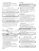
Name Device

An unnamed MM 42 will default with this display:

RANE CORPORATION MM 42
PERSONAL MONITOR PROCESSOR        STORE

1. Rotating the DATA control under each character lets you

rename your unit to anything you wish. Use the 

 and

keys to move between character fields. A total of 52

characters (2 lines of 26 characters each) is permitted.

2. Press ENTER to move the cursor to the STORE field. Press

ENTER to complete the operation.

The Name Device operation can be cancelled at any time

by pressing the CANCEL button.

Firmware Update

Firmware updates may be made available periodically to

address new features or fix reported problems. You can
perform the update using any MIDI device capable of playing
back a downloaded MIDI SysEx data file.

You can run the firmware updater file using any computer

equipped with a MIDI interface. In Windows, the default
.MID player (such as Windows Media Player) works if the
correct MIDI output is selected in Control Panel > Sounds
and Audio Devices > Audio > MIDI Music Playback. Refer
to your MIDI software or interface instructions.

To update firmware:

1. Download the latest firmware MIDI file (MM42*.MID)

from 

www.rane.com/mm42.html

.

2. Press the UTILITIES button several times until the

UPDATE DEVICE FIRMWARE page is displayed.

3. Rotate the DATA control to select YES and press ENTER.

UPDATE DEVICE FIRMWARE? YES
CURRENT FIRMWARE VERSION *.*

4. Re-confirm the action. Rotate the DATA control to select

YES and press ENTER.

UPDATE DEVICE FIRMWARE:
ARE YOU SURE? YES

The MM 42 eagerly awaits for the incoming data…

AWAITING MIDI DATA

PRESS CANCEL TO ABORT

5. Now play the MM42*.MID file. When incoming MIDI

data is detected the MM 42 displays…

FIRMWARE DOWNLOAD IN PROGRESS

…then wait while the firmware is loaded...
…followed by a success message with the new version:

MM 42 FIRMWARE UPDATE SUCCESSFUL

VERSION *.*

On the 

transmitting

 MM 42:

1. Select SEND mode on the MIDI TRANSFER page.
2. Select the MEMORY (1 through 16 or ALL) location to

send to the receiving MM 42.

3. Select the SEND action (flashing) and press ENTER. The

following screen appears:

SENDING MIDI DATA

When incoming MIDI is detected the receiving MM 42 says:

RECEIVING MIDI DATA

When the transfer is complete both units display:

MIDI TRANSFER COMPLETE

PRESS CANCEL TO CONTINUE

If the following horrifying display appears on either unit

during the transfer there has been an error. Don't get mad, just
check all connections and settings and try again:

MIDI TRANSFER FAILED

PRESS CANCEL TO CONTINUE

TIP: Memory locations in the transmitting device can be

stored to any Memory location in the receiving device. For
example, the screens  to store Memory location 1 from the
transmitting device to Memory location 3 in the receiving
device (so as not to overwrite Memory 1 in the receiving
device) would be as follows:

Transmitting MM 42:

MIDI   | MODE      MEMORY
TRANSFR| SEND          1        SEND

Receiving MM 42:

MIDI   | MODE      MEMORY
TRANSFR| RECEIVE       3     RECEIVE

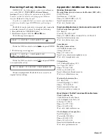
Backing up Memories to a PC or other MIDI Device

Be sure the MIDI Tx of the MM 42 is 

not

 set to off.

1. Connect the MIDI OUT of the transmitting MM 42 to the

MIDI IN of the receiving MIDI device.

2. Place the receiving device into “record” or “receive” mode.

Memories are stored as MIDI System Exclusive (SysEx)
data, so be sure to turn off any SysEx filters that may be in
place during record or playback. Consult the Owner’s
Manual of your MIDI device.

On the 

transmitting 

MM 42:

3. Select SEND mode on the MIDI TRANSFER page
4. Select the MEMORY (1 through 16 or ALL) location to

send to the receiving MIDI device.

5. Select the SEND action (flashing) and press ENTER.

The screens are the same as when transmitting between

MM 42s (see above).

Summary of Contents for MM 42

Page 1: ...page Adjust the THRSH parameter until you see a few blinky lights on the Gain Reduction meter Press the COMPRESS button again to move on to band 2 and again to move to 3 merrily making adjustments No...

Page 2: ...parameter Turning the DATA control clockwise increases the parameter and turning it counterclockwise decreases the parameter Push and turn the DATA control for fine adjustment of some param eters The...

Page 3: ...to the front panel PHONES jacks The Cue Out level is not affected by the Phones Level control CUE BUS jacks are RJ 12 telephone style for interconnecting multiple MM 42s for cueing soloing purposes M...

Page 4: ...0 2 4 8 6 PUSH FINE PUSH SELECT MM 42 DATA OUTPUT INPUT PHONES GAIN REDUCTION CONFIG FILTER SUB A MEMORY UTILITIES CUE BUS B C D 1 2 LEVEL COMPRESS EQ LIMIT ENTER CANCEL ACME In Ear Stereo Transmitter...

Page 5: ...CME In Ear Mono Transmitter 2 or wired beltpack Input OR LINE INPUT A LINE INPUT B OUTPUT 1 OUTPUT 2 36 dBFS PEAK 8 12 24 dBu dBu 0 3 4 8 12 24 0 3 4 PROCESSOR MONITOR 10 12 24 8 10 3 1 6 4 36 12 24 8...

Page 6: ...BUS CUE BUS CUE BUS Monitor Engineer ACME Mixing Console Stereo Transmitter Background Vocal 1 Stereo Transmitter Background Vocal 2 36 8 12 24 0 3 4 8 12 24 0 3 4 PROCESSOR MONITOR 10 12 24 8 10 3 1...

Page 7: ...lows Range Coarse Fine 20 999 Hz ISO centers 20 800 Hz 1 Hz 1 0 kHz 9 9 kHz ISO centers 1k 8k 0 1 kHz 10 kHz 20 kHz ISO centers 10k 20k 1 kHz If a frequency is currently set to a non ISO value making...

Page 8: ...o t B d 0 0 4 r o f f o l e v e l t u p t u o o e r e t S T U P T U O n r u T t n e m t s u j d a s t n e m e r c n i B d 1 r o f l e v e L B d 5 0 r o f n r u t d n a h s u P s t n e m e r c n i E C...

Page 9: ...ER 3 BAND PEAK LIMITER OUTPUT LEVEL OUT 2 SUB OUT 1 INPUTS A B C D 8 12 24 0 3 4 8 12 24 0 3 4 Block Diagram Main Inputs Outputs and Sub Output Signal Processing Overview So what does the MM 42 have u...

Page 10: ...i a g h g i H y l n o e d o m f l e h S o t B d 5 1 B d 2 1 t s o o b r o t u c f o t n u o m A Description Shelf Cut Filters tailor the upper and lower frequency ranges of personal in ear monitors A...

Page 11: ...h F N I K C T A k c a t t A o t s m 5 0 s m 0 0 1 e h t y l k c i u q w o h s e n i m r e t e D e c n o d e c u d e r s i e m u l o v t u p t u o e h t s d e e c x e e m u l o v t u p n i e h t d l o...

Page 12: ...lly instead of selecting OUT1 2 Figure 3 Parametric EQ various Q settings 20 20 18 16 14 12 10 8 6 4 2 0 2 4 6 8 10 12 14 16 18 4 4 3 5 3 2 5 2 1 5 1 0 5 0 0 5 1 1 5 2 2 5 3 3 5 d B Hz Important note...

Page 13: ...M 42 it doesn t matter which one and press the front panel CUE BUS button on the unit you wish to monitor The signal from that unit is automatically routed to the Cue Bus and can be monitored from any...

Page 14: ...e e w t e b s t c e l e S e d o m s u B e u C y r a t n e m o m Repeatedly pressing the UTILITIES button cycles through the following useful pages Cue Bus Configuration CUE BUS CUE PHONES PROCESSING M...

Page 15: ...d pre or post processing This feature is especially useful for doing a before and after comparison to hear the effect of the channel processing and only affects the Phones and CUE Outputs the Main Out...

Page 16: ...e firmware is loaded followed by a success message with the new version MM 42 FIRMWARE UPDATE SUCCESSFUL VERSION On the transmitting MM 42 1 Select SEND mode on the MIDI TRANSFER page 2 Select the MEM...

Page 17: ...es Hearing Conservation Hearing Education Awareness for Rockers H E A R PO BOX 460847 San Francisco CA 94146 Phone 415 409 EARS or 3277 Email hear hearnet com Web www hearnet com Earphone Manufacturer...

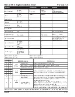
Page 18: ...o P n O i n m O 1 e d o M y l o P f f O i n m O 3 e d o M o n o M n O i n m O 2 e d o M o n o M f f O i n m O 4 e d o M Version 1 2 r e l l o r t n o C r e t e m a r a P 2 4 M M e g n a R I D I M c e...

Reviews: