Manual-3
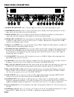
MAIN & REMOTE MIC OVERLOAD indicator:
Monitors
both Microphone Inputs
, before and after the MIC EQ. It
lights whenever these levels exceed 4 dB below clipping.
Occasional flickering is normal; however, it should not be
allowed to light steadily
.
MAIN MIC ENGAGE switch:
When pressed, ENGAGES the MAIN MIC Input. The adjacent red LED flashes whenever
the switch is pressed
in,
signalling that the Main Mic is
on
.
MAIN MIC LEVEL control:
Adjusts the Level of the front panel MAIN MIC Input.
REMOTE MIC LEVEL control:
Adjusts the Level of the rear panel REMOTE MIC Input.
CROSSFADER CONTOUR control:
Allows adjusting the “shape” of the CROSSFADER response from a gentle curve
for smooth, long running fades, to the steep pitch required for top performance cut and scratch effects. See Figure 1 on page
Manual-1.
ÿ
A & B Input Channel faders
: Control the Levels of the Input selected on each Channel.
ACTIVE CROSSFADER:
Controls the relative level of the Inputs assigned to the A and B Channels. When this fader is at
its far left, only Channel A is heard from the Outputs. As the fader is moved toward the right, the volume of Channel B is
increased. When the fader is centered, both Channels deliver equal volume. As you might expect, at the far right only
Channel B is heard from the Outputs. In the unlikely event of Crossfader trouble, See
Replacing the Active Crossfader
below. See Figure 1 on page Manual-1 for response curves of various contour settings.
MASTER LEVEL fader:
Determines the final Level at the MASTER and ZONE OUTPUTS. Unity gain is around “6”.
HEADPHONE PAN control:
Serves two purposes. When the Headphone Mode switch (see
) is in STEREO mode, this
controls the relative levels of the Cue and Program mixed together in Stereo. When the Mode is switched to MONO, this
controls the balance between Mono Cue in the left earcup and the Mono Program in the right.
HEADPHONE LEVEL control:
Clockwise rotation of this rotary control increases the Headphone drive Level.
HEADPHONE mode switch:
In the
out
position, this switch feeds Stereo Cue and Program to both earcups. In the
in
position the headphone circuit provides Mono Cue to the Left ear and Mono Program to the Right ear.
HEADPHONE Output jack:
A ¼" tip-ring-sleeve stereo jack delivers signal to stereo headphones.
POWER “ON” indicator:
Illuminates when the MP 22z is connected to an appropriate power source (see Rear Panel
).
FADER CLEANING
With heavy use in harsh environments, the faders may
need lubrication. This treatment extends longevity and can
make used faders as good as new. The fader assembly must
be removed from the MP 22z for proper cleaning. We
recommend any of the following cleaning solutions:
Caig Cailube MCL 100% spray lubricant
Caig Cailube MCL 5% spray cleaner
CRC 2-26
Order CaiLube MCL
®
from:
CAIG Laboratories, Inc.
12200 Thatcher Ct.
Poway, CA 92064
Phone 619-486-8388
Fax 619-486-8398
Web
http://www.caig.com
REPLACING THE ACTIVE CROSSFADER
The Crossfader may be removed without any disassembly
of the MP 22z itself, and may be performed while the unit is
operating with no interruption of the audio signal.
F 60 and F 45 Fader Kits are available from your local
retailer or the factory. The kit includes full assembly includ-
ing knobs, ribbon, and face plate.
1. Remove the two (2) outer screws attaching the crossfader
assembly to the front panel.
2. Pull the Crossfader Assembly forward and unplug the
ribbon from the connector on the bottom board.
3. Proceed with Cleaning Instructions, or install the replace-
ment assembly by reversing the above instructions.
CLEANING INSTRUCTIONS
1. Hold the fader assembly away from the mixer.
2. Position the fader at mid-travel.
3. Spray cleaner/lubricant into both ends of the fader.
4. Move the fader over its full travel back and forth a few times.
5. Shake excess fluid from the fader assembly.
6. Wipe off excess fluid.


