Manual-12
PROGRAMMING THE RPM 26
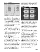
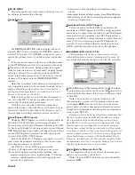
Each DSP Program contains a number of processing Blocks. There is a Block shown for each available signal process-
ing function. The quantity and type of available processing blocks varies from DSP Program to DSP Program.
Double clicking on most of these processing Blocks opens a detail window where most processing settings are edited.
Assuming your computer screen provides enough graphics resolution, up to three of these detail windows can be open at
any one time. In addition, a fourth window that displays the
Overall Response
curve for a given output can be opened by
double-clicking any output’s screw terminal graphic. Once a detail window is opened, settings can be edited. The window
can then be closed and the changed settings are retained in the working memory (memory zero). Changes are not stored in
any other memory until you save them with the
Store
button.
It is not possible to
Alt-Tab
to another Windows application while any RPM Detail Window has the focus. You can,
however,
Alt-Tab
from the RPM’s main Device Edit screen when it has the focus. This allows you to toggle between
Windows applications and still keep the RPM’s Detail Windows open on the screen.
INPUT TRIM
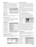
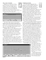
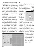
The Input Trim processing block is on the
left side of the Device Edit screen, just to the
right of the input screw terminal. This block is
shown here:
The Input Trim operates the RPM’s
internal analog level control whose sole
purpose is to provide the analog-to-digital converter with the
proper voltage level. Click on the up and down arrows to
increment or decrement the Input Trim.
For more precise control of the Input Trim, double click
on the Input Trim block. You may double click anywhere
except on the arrows or on the Mute button to open the detail
window, shown below.
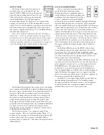
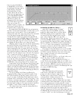
The name of the processing block appears at the top of
each detail window, in this case, input
Trim A
. The horizontal
scroll bar adjusts the Trim control in three ways. Clicking the
left or right arrows adjusts the trim in ½ dB steps. Clicking
between the arrows and the sliding box (Thumb) adjusts the
Trim in 5 dB steps. Clicking and holding the Thumb allows
you to drag the control.
Two meters are shown in the Input Trim detail window.
The
Input
meter on the left shows the voltage level (in dBu) at
the screw terminal input of the RPM 26. Adjusting the Trim
control has no effect on this Input meter. Clicking the input
Mute
button turns this meter off, even though Input signal
may still be present. (The front panel’s
Input signal present LEDs always show the
presence of incoming audio, ‘pre-trim.’)
The
A/D
meter on the right shows the A/D
level (in dB Full Scale), and indirectly
shows the number of bits being toggled by
the input signal after passing through the
input level control. Clicking the
Mute
button also turns this
A/D
meter off.
To set the Input Trim, please read the
rest of this section and the A/D, D/A &
METERING section below. With the
amplifiers turned down or off and all of the
RPM’s outputs muted, apply your system’s
expected average audio level to the RPM
26. The Input meter displays this voltage as
long as the Input
Mute
is not active and the
level is not set too high (clipping). The
RPM 26 is designed to r20 dBu of
input and send the same +20 dBu out. This +20 dBu is
designed to be zero dB Full Scale (
dBFS
) at the A/D con-
verter (i.e., maximum input to the A/D converter) when the
Input Trim is set to
0.0dB
. Set the Input Trim so your
nominal signal level lights the
A/D
meter indicator corre-
sponding to your system’s required headroom.
For example, let’s assume your system requires 16 dB of
headroom. Set the Input Trim until the -16 dB
A/D
meter
indicator lights with an average signal level present. This
corresponds to a nominal input signal level of +4 dBu. If you
run a system with less headroom, let’s say 12 dB, set the
Input Trim until the -12 dB
A/D
meter indicator lights. This
corresponds to a nominal input signal level of +8 dBu. If you
tend to use a lot of EQ boost at mid or especially low frequen-
cies, turn the Input Trim control down to compensate for the
low frequency boost. Refer to the enclosed RaneNote “Setting
Sound System Level Controls” for more information.
The Input Trim control should never be set such that your
highest signal peaks toggle the
A/D
meter’s
+0 dBFS
indicator. This is where the A/D converter clips. The RPM
clips cleanly. It is important to toggle as many bits as possible
on the A/D converter. Toggling as many bits as possible is
precisely equivalent to maximizing signal-to-noise ratio in
analog audio systems. The Input Trim should never be used as
a “system” level control. This is why there is only 12 dB of
attenuation available on the Input Trim.
If the functionality of the
Input Mute
button is unclear, perhaps trying to explain
it would be moot. Remember that the signal
ramps back to its setting after unmuting
unless ramping is disabled.
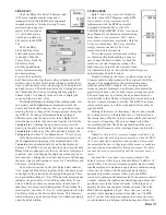
When checked, the Input Trim
Linked
check box “ties” the two Trim controls
together. (The Mute buttons can not be
linked.) Both Input
Linked
boxes must be
checked in order for the controls to
function together. This functionality
provides a
Linked
or “stereo” Input Trim
and also permits offsetting the two con-
trols, then linking them. A red ‘
1
’ appears
in the Input Trim block on the Device Edit
screen when the
linked
box is checked.
This indicates the control is linked without
needing to open the detail window.

