Manual-20
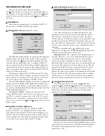
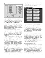
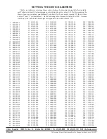
In addition to the individual signal processing blocks
described above, the RPM 26 contains
Input
Blocks and
Output
Blocks, shown above. These terms simply describe a
subset of the available processing blocks and allow conve-
nient copying of settings from multiple processing blocks.
For example, once you’ve properly set up one-half of a stereo
3-way speaker stack, right mouse click on any output process-
ing block that you’ve already tweaked. A menu appears that
permits clipboard copying of all of the
Output
Blocks’
settings (
Copy Output Settings
). This includes the settings
for the Fine Delay, PEQ, Trim and Limiter. Then right click
on the corresponding
Output
Block for the other speaker
stack. The pop up menu appears again allowing you to paste
(
Paste Output Settings
) all the settings from the previously
tweaked Delay, PEQ, Trim and Limiter. Then do the same for
the other two loudspeaker drivers and you have a great
starting point to properly adjust the other speaker stack. The
Input
Block provides this same
Cut
and
Paste
functionality.
COPY & PASTE
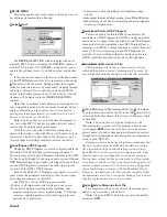
To copy any individual signal processing block’s current
settings to another corresponding block, right click on it.
(You may right click on any small Device Edit screen block
or on any block’s Detail Window to copy and paste settings.)
Select Copy from the menu — the settings are now stored for
pasting. Then, right click on the block you wish to paste the
copied settings to and select Paste from the menu. You’re
done! See the above section for copying entire Input or
Output block settings.
OUTPUT BLOCKS
INPUT BLOCKS &
GENERATOR (PINK NOISE OR SINE)
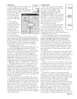
Pink
Noise or
Sine
wave signals are
available in some DSP Programs. A ‘
G
’
appears in the simple graphic in the
Choose
DSP Program
window, indicating that a
given DSP Program supports these
G
enerator
test signals. The
Pink
Noise is provided as a
test signal for listening to comb filtering in speaker arrays or
for listening for room reflections. The
Sine
wave provides a
convenient test signal, helpful in setting gain structures or for
more accurately hearing specific-frequency room reflections.
The signal
G
enerators default to a
Mute
d state when new
DSP Programs containing
G
enerators are requested. Click
Mute
to unmute the Generator. Click the up or down arrows
to adjust the
G
enerator’s
Level
in ½ dB steps. The maximum
attenuation is 40 dB. The
G
enerator levels are calibrated in
dBFS, i.e. at 0dB the
G
enerator is sending a full scale digital
signal to the D/As.
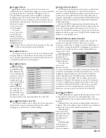
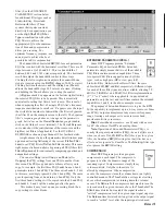
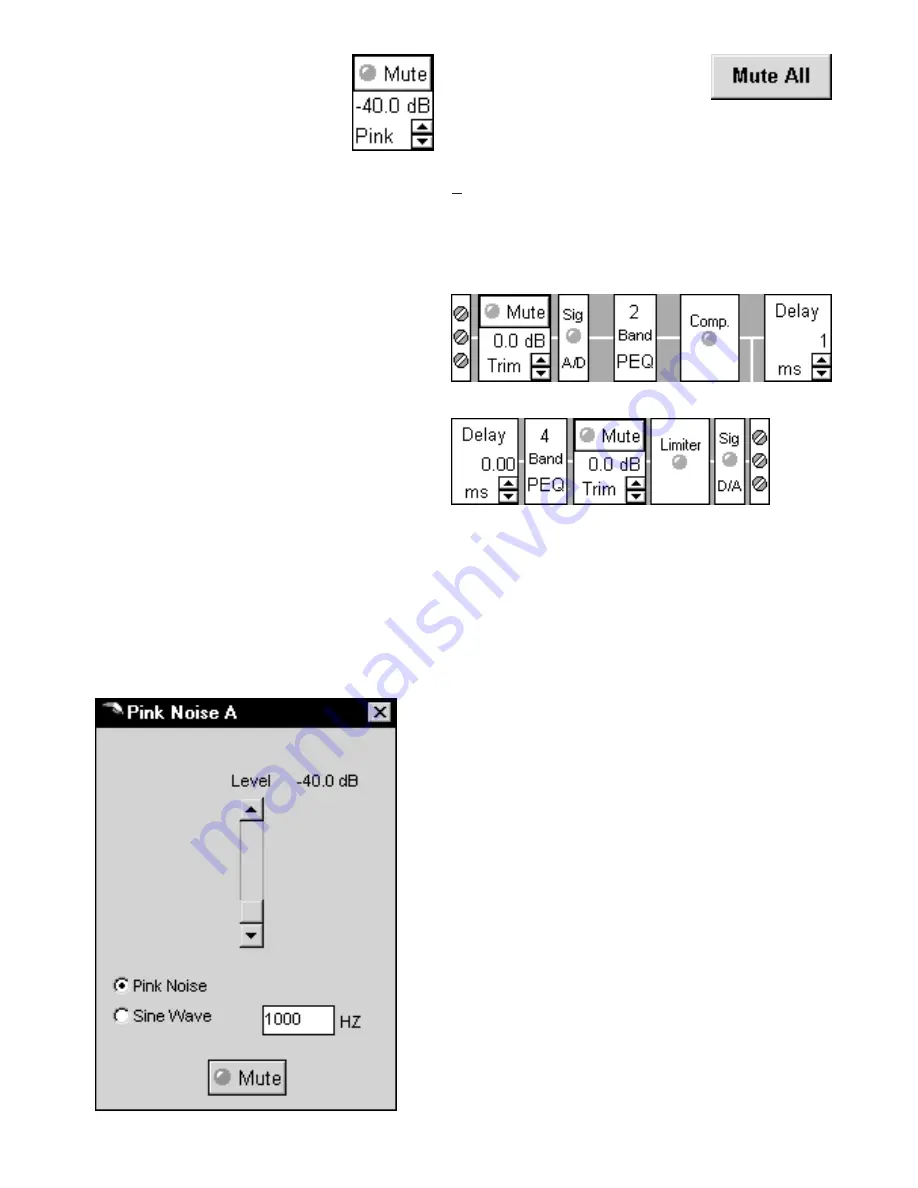
Double-click on the
G
enerator block to open the detail
window. A vertical scroll bar adjusts the Level in three ways.
Click and drag the Thumb directly, click between the Thumb
and the arrows for 5 dB steps or click on the up or down
arrows for ½ dB steps.
Radio buttons on the left allow selection of
Pink Noise
or
Sine Wave
as the
G
enerator source. If
Sine Wave
is se-
lected, the edit box to the right dictates the
Sine Wave
frequency in Hertz. One Hertz steps are accepted.
DSP Programs with two
G
enerators contain two
uncorrelated pink noise sources, required when you wish to
listen to “stereo” pink noise signals. Also, the two sine wave
generators are not guaranteed to be in phase. Be sure to
always
Mute
the RPM’s
G
enerators any time you use an
analyzer for system measurements, since the analyzer must
use its own internal generator for such measurements.
MUTE ALL
The
Mute All
button is provided for
those moments when you quickly need
to turn all of the RPM’s outputs off.
Please note that once all outputs are muted, clicking
Mute All
again does not unmute all of the outputs. All outputs are also
muted each time you choose a new DSP Program from the
Device
menu’s
Choose DSP Program
option. This pur-
posely forces the user to unmute each output separately and
allows one to reflect on the consequences of unmuting each
output independently.

