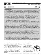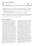
Manual-3
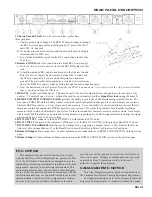
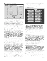
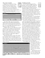
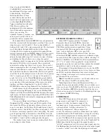
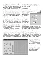
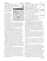
REAR PANEL DESCRIPTION
FCC NOTICE
This equipment has been tested and found to comply
with the limits for a Class B digital device, pursuant to Part
15 of the FCC Rules. These limits are designed to provide
reasonable protection against harmful interference when the
equipment is operated in a commercial environment. This
equipment generates, uses, and can radiate radio frequency
energy, and if not installed and used in accordance with the
instruction manual, may cause harmful interference to radio
communications. Operation of the equipment in a residen-
tial area is likely to cause harmful interference in which
CANADIAN EMC NOTICE
This Class B digital apparatus meets all requirements of
the Canadian Interference-Causing Equipment Regulations.
Cet Appariel numerique de la classe B respecte toutes les
exigences du Reglement sur le material broilleur du Canada.
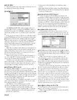
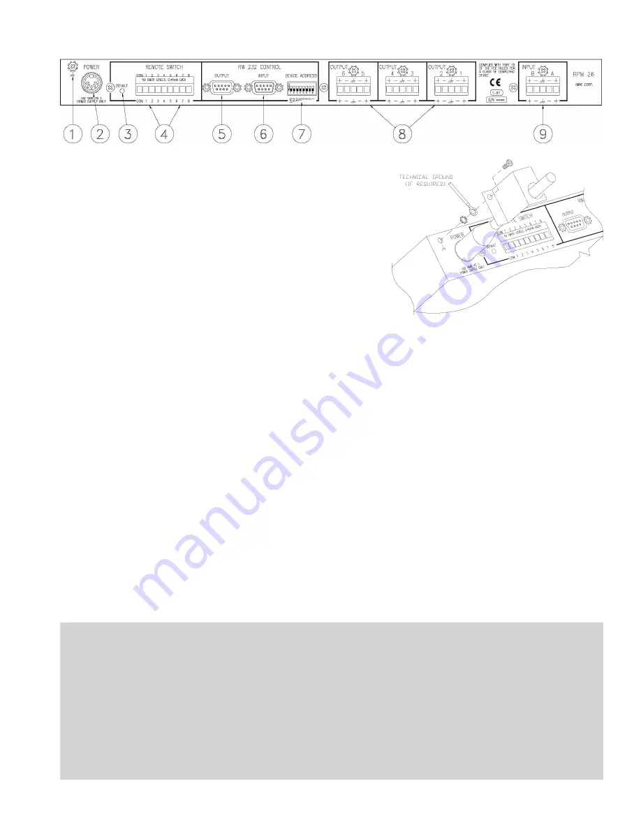
1. Chassis Ground Point This 6-32 screw and star washer have
three purposes:
A. Chassis ground when needed. The RPM 26 chassis connects through
the RS 3 power supply cables to earth ground (3
rd
pin) of the 100V
and 120V AC line cord.
B. It can also provide a technical ground connection if needed, (highly
recommended for 230V use).
C. It is also the attachment point for the RS 3 captivation bracket. (See
#2 below.)
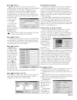
2. Remote POWER jack is for connection to a Rane RS 3 power supply.
A. With the AC power disconnected, insert the RS 3 DIN plug into this
jack.
B. Attach the included RS 3 captivation bracket to the Chassis Ground
Point (#1 above). Install the star washer between the bracket and
the Chassis (especially if you are using this point as a technical
ground). The star washer helps guarantee a reliable electrical connec-
tion to the RPM 26’s chassis metal by biting through the non-conductive paint.
C. Now the unit is ready for AC power. To power the RPM 26 up and down, it is wiser to cycle the AC power cord, rather
than to unplug and plug the DIN jack.
3. DEFAULT switch recalls Memory 1. This may be useful in case of computer failure and duplicates the function of the
number ‘1’ Remote Memory Switch—without the need for an external switch (See Signal/Overload on page Manual-2).
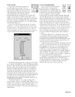
4. REMOTE SWITCH INTERFACE (RSI) provides the ability to recall one of 8 Memories using contact closures. The
front panel COM LED flashes briefly whenever the RSI switch configuration changes. Since each memory can contain a
different DSP Program (i.e., a 2-way crossover in one memory, 3-way in another), in a fixed installation, be sure that all
memories contain the appropriate DSP Programs for your system. This avoids the problem of accidentally recalling a
memory which could be detrimental to the system. On the other hand, this feature is useful in rental systems, for example,
where fixed DSP Programs can be stored in various memories requiring only an RSI wiring alteration to change the signal
processing from a 2-way to a 3-way system.
5. RW 232 OUTPUT connects to the RW 232 INPUT on other Rane RW 232 units.
6. RW 232 INPUT connects to the computer’s COM port, or to the RW 232 OUTPUT of the previous Rane RW 232 unit.
7. RW 232 DEVICE ADDRESS identifies each unit uniquely by assigning it a number from 1 to 250. Refer to the Device
Address Table on page Manual-22 or the RaneWare Address Calculator software for binary switch positions.
8. Balanced Outputs. No surprises here. Connect balanced audio connections as in RPM 26 CONNECTION on the previous
page.
9. Balanced Inputs. Connect balanced audio connections per the RPM 26 CONNECTION section on the previous page.
case the user will be required to correct the interference at
their own expense. Changes or modifications not expressly
approved by Rane Corporation could void the user’s
authority to operate the equipment.

