background image

Manual-4

SOFTWARE OPERATION

STARTING RANEWARE

If RaneWare has not yet been installed on your computer,

refer to STEP BY STEP RANEWARE INSTALLATION
above. Once the software is installed, a RaneWare Program
Group is created with four icons. One icon each for the
RaneWare application, Help, Address Calculator, and
Manual. The RaneWare umbrella icon launches device
control, Help provides extensive on-line assistance, the
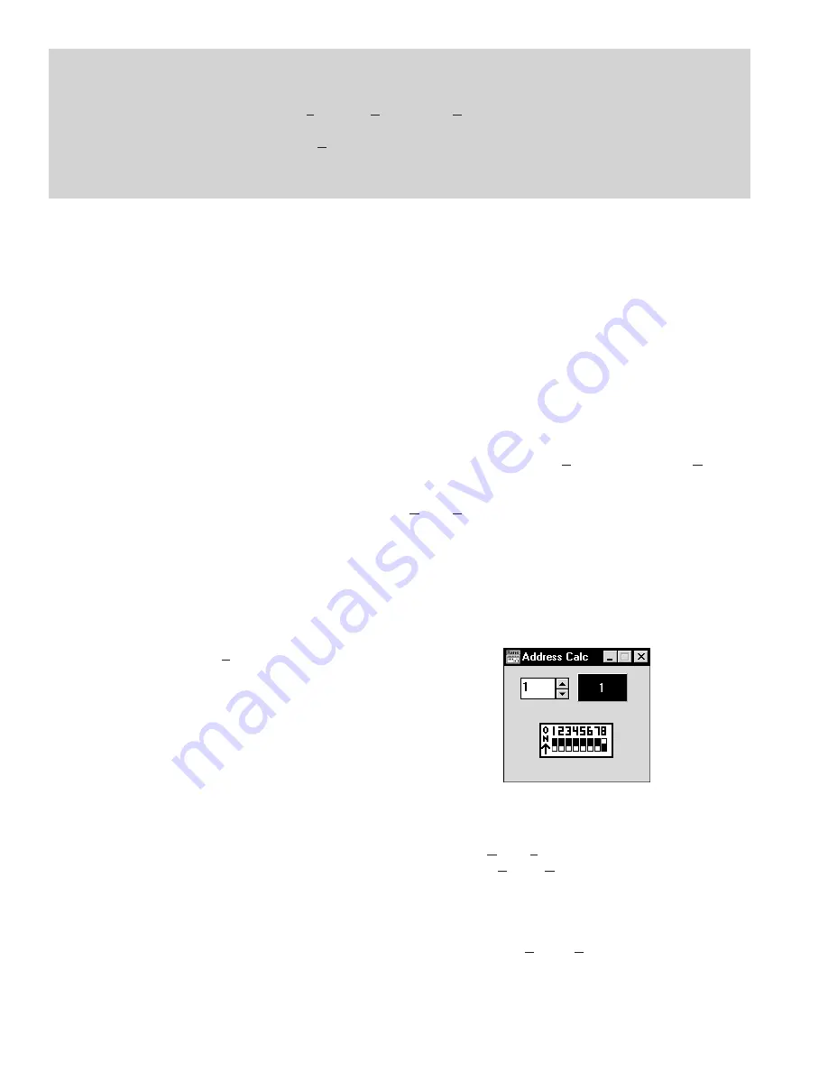
Address Calculator software makes selecting RW 232
device addresses easy and the Manual icon contains the
manual for the RPM 26 and the other RW232 products.

When the Device Control software is first run,

RaneWare’s Help screen displays Rane’s Software License
Agreement. The License Agreement is contained in the Help
file, so you can continue to browse for helpful details before
continuing. Once you’ve read the License Agreement, close
the Help file. After you’ve selected a Com port, subsequent
activations do not bring up the Help screen unless you ask for
it. Now let’s get on with the program. Double-click the
RaneWare umbrella icon.

Welcome to RaneWare! A splash screen displays for a

few seconds, then the 

Device Select

 window or an 

RW 232

Device Edit

 screen appears. To try the software without a

unit hooked up, select the 

OFFLINE RPM 26

 and click 

OK

or to control a real RPM, click 

Poll

, and polling for units

begins. This process checks if any units are connected to the
serial port. If a Device is found, you are in control! If you
have a device hooked up and it is not found, read the
TROUBLESHOOTING section on page Manual-21 or see
the Help file.

There are multiple RaneWare products available from the

RaneWare software screen. They include the RPM 26, the
RPE 228, a 2-channel, one-third octave equalizer, and the
ECS line of Engineered Conference Systems products for
teleconferencing and distance learning applications.

RW 232 BASICS OVERVIEW

All RW 232 devices, including the RPM 26, contain a

“current” or working memory (memory zero) and 16 addi-
tional memories where the current settings may be stored and
recalled. All of these memories exist inside the device, not
inside the computer controlling the device. Thus, if the
computer crashes, the unit continues to operate and keeps its
current settings. If the unit loses power, all current settings
are saved and automatically recalled upon power up — unless

an RSI contact switch has changed positions while the power
was off, then it recalls the selected RSI memory.

The Windows screens perform the traditional function of

a front panel, displaying and editing the device’s settings. For
example, the Store button tells the unit to copy its current
settings (Memory zero) into a specific memory number (let’s
say, Memory 4).

Use the RaneWare Button Bar to store and recall memo-

ries. (See THE RANEWARE BUTTON BAR section on page
Manual-10 for more details.)

Devices can also be given custom names, tailored to your

installation. Simply choose 

Name Device

 from the 

Device

menu (see page Manual-9).

If your installation changes by adding more units, choose

Device|Select

, and the 

POLL

 button to make the computer

recognize new units in the system.

When multiple units are connected, assign each unit a

unique Device Address number. Rane provides a special
calculator to assist in setting the DIP switches on the back of
each unit. In the RaneWare Program Group, launch the
RaneWare Address Calculator. This binary calculator
converts decimal numbers into corresponding DIP switch
settings and vice-versa.

SECURITY

The RPM can be operated on a daily basis either through a

computer or through the contact closures. To preserve preset
security during computer operation, each device can be
locked (under 

Device|Lock Device

), and a password can be

assigned (under 

System|Change Password

). The default

password is please. Passwords are case insensitive, therefore,
PlEASe, pLEasE, PLEASE and please are all equivalent.

With a device locked, no settings can be changed; only

preset memories can be recalled. Presets can be customized
with names (through 

System

Site Control Panel Setup

).

Each memory can have a logical name. The Site Control
Panel is all an operator needs to see to recall memories. If

STEP BY STEP RANEWARE INSTALLATION

1. If you have the RaneWare 3.5" floppy disk, insert it in your drive.
2. In Windows 3.1 Program Manager, under 

File

, select 

Run

.... On the 

Command Line

:, type 

A:\install

. (Use the drive

letter that matches your 3.5" drive, some systems use 

B:

 instead.) Click 

OK

. Installation begins.

3. In Windows 95, from the 

Start 

menu, select 

Run....

 Under 

Open:

, type 

A:\install

. Click 

OK

. This starts installation.

4. If you downloaded RaneWare from the web, decompress the RaneWare 

.zip

 file first. Locate the now uncompressed

install.exe

 file and run it. Installation proceeds.

Summary of Contents for RPM 26

Page 1: ...ue address for each unit Apply power by connecting the RS 3 remote supply s 5 pin DIN jack to the rear of the unit then connect the IEC end to a powered AC outlet CAUTION Do not connect anything but a...

Page 2: ...e cable shields to the center terminal on the Euroblock For those installations where the RPM s internal shield to chassis connection causes interference connect the shields directly to the chassis PE...

Page 3: ...ve paint C Now the unit is ready for AC power To power the RPM 26 up and down it is wiser to cycle the AC power cord rather than to unplug and plug the DIN jack 3 DEFAULT switch recalls Memory 1 This...

Page 4: ...l current settings are saved and automatically recalled upon power up unless an RSI contact switch has changed positions while the power was off then it recalls the selected RSI memory The Windows scr...

Page 5: ...K Each unit s Device Address will be displayed within brackets 1 to the left of the device name Double clicking on the device name is equivalent to selecting the device and clicking OK THE RANEWARE SC...

Page 6: ...iagnostics of RW 232 AMX or Crestron systems Thus from the office a system designer can call a properly equipped remote system to view and control that system s RW 232 settings System Change Password...

Page 7: ...anual for detailed instructions Important Note The names you assign become the memory names associated with each RW 232 device on line regardless of the type of device RPM 26 RPE 228 ECS Teleconferenc...

Page 8: ...OK or just double click on the device The Device Edit window for the device you ve selected appears allowing complete control of the device Device Choose DSP Program Choosing DSP Programs is covered...

Page 9: ...ings from a stored file instead of a connected unit This allows you to setup a system save the system s settings to a file and print them at your office saving you the hassle of dragging your printer...

Page 10: ...Help About is very important if you ever need RPM 26 or RaneWare technical support from Rane RPM 26 BASICS The RPM 26 has 2 inputs named Input A and Input B and 6 outputs named Output 1 through Outpu...

Page 11: ...on A few lines describing each DSP Program are listed Generally these descriptions duplicate information available in the simple graphic but some DSP Programs provide much greater functionality than t...

Page 12: ...r on the right shows the A D level in dB Full Scale and indirectly shows the number of bits being toggled by the input signal after passing through the input level control Clicking the Mute button als...

Page 13: ...te as reliable as possible The A D and D A blocks on the RPM 26 Device Edit screen indicate where in the signal chain the A D and D A conversions occur These blocks also contain the signal present and...

Page 14: ...t or view The Freq Hz edit box is changed with the up or down arrows Or click in the edit box to display the cursor and type a new frequency value always in integer Hertz The Level dB edit box is also...

Page 15: ...qualization can use the High Shelf PEQ Filter Type in combination with other PEQ filters to achieve the appropriate EQ for the combina tion of horn and compresssion driver you are using For optimum fr...

Page 16: ...ompressor threshold has been reached All other Compressor settings are adjusted in the Compressor detail window shown at the bottom of this page Double clicking on the Compressor block opens the detai...

Page 17: ...ssover blocks are found in various DSP Programs in the RPM Up to a mono 6 way crossover can be implemented with the RPM s powerful Extended Parametric EQ see the EX TENDED PARAMETRIC PEQ section on pa...

Page 18: ...fiers and speakers This avoids the potential catastrophe of slipping with the mouse or reaching again for your latt and accidentally clicking the mouse SUMMING AND I O ROUTING Some DSP Programs provid...

Page 19: ...the various filter sections in the RPM 26 The graph in the example above does not show the contribution of the crossover since the Crossover box is unchecked LIMITER For most DSP Programs each output...

Page 20: ...st signals The Pink Noise is provided as a test signal for listening to comb filtering in speaker arrays or for listening for room reflections The Sine wave provides a convenient test signal helpful i...

Page 21: ...he RW 232 INPUT jack on the rear of the unit Be sure the Remote to RPD 1 box is not checked in the System System Setup menu This box is only used with the Rane RPD 1 to remotely communicate with an RW...

Page 22: ...01100001 98 01100010 99 01100011 100 01100100 101 01100101 102 01100110 103 01100111 104 01101000 105 01101001 106 01101010 107 01101011 108 01101100 109 01101101 110 01101110 111 01101111 112 0111000...

Reviews: