Manual-15
PARAMETRIC EQ (PEQ)
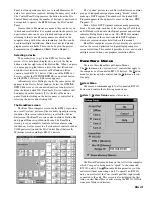
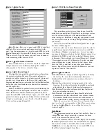
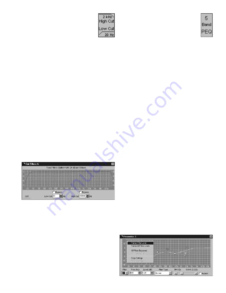
Every DSP Program contains multi-band
parametric EQ, abbreviated
PEQ
. The quantity of
PEQ filters varies from program to program. The
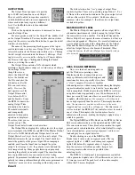
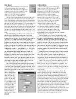
PEQ block shown at the right contains 5 filters.
Some DSP Programs have parametric EQ in both
the Input and Output (see Input Blocks & Output
Blocks on page Manual-21). Parametric EQ can be used for a
wide variety of purposes. Generally, input parametric is used
for program sweetening and/or band-limiting the frequency
range. Output parametric can be used to correct for loud-
speaker response anomalies, or if used sparingly, to some-
times overcome acoustically created room anomalies. In
distribution applications, output PEQ provides independent
equalization of each zone.
The quantity of PEQ filters may vary with each program,
but the operation of the PEQ filters is consistent. Double
clicking on any
PEQ
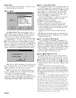
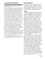
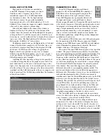
block opens that PEQ’s detail window
where all parametric parameters are adjusted. The detail
window is shown at the bottom of this page.
The name of the open
PEQ
block appears at the top of the
window. The graph contains some quantity of circled num-
bers, each representing an available parametric EQ filter. The
location of each circle on the graph determines that filter’s
frequency in the
x
-direction (left-right) and level (boost/cut)
in the
y
-direction (up-down). Across the bottom of the screen
are edit boxes displaying the selected filter’s current settings.
The left-most
Filter
edit box displays the currently selected
filter number. This same filter appears on the graph in a
different color with its corresponding number circled. The
plotted contribution of the selected filter also appears in a
different color. This makes it easier to see the contribution of
each individual parametric filter. It is also convenient to
simultaneously open the
Overall Response
curve for the PEQ
output you are viewing (double click on the Output’s screw
terminal). This provides the calculated overall response of all
viewed PEQ filters. (See the Overall Response section on
page Manual-20 for further details.) Click on the
Filter
edit
box’s down arrow to display and select a different filter’s
settings. You may also click directly on the circled number on
the graph corresponding to the filter to edit or view it.
The
Freq (Hz)
edit box is changed with the up or down
arrows. Or click in the edit box to display the cursor and type
a new frequency value, always in integer Hertz.
The
Level (dB)
edit box is also changed with its up or
down arrows. Or click in the edit box to display the cursor
and type a new level value in dB. The
Level
’s step size is ¼
dB (0.25). The boost range is +12 dB, the cut range is -15 dB.
Typed values are
truncated
to the nearest value,
not
rounded
high or low.
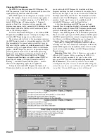
HIGH & LOW CUT FILTERS
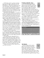
High and Low Cut filters are provided in
some DSP Programs. Their purpose is to band-
limit the system’s frequency range. Not all
installations require 20 to 20 kHz bandwidths
for their audio systems. Use the
High
and
Low
Cut
filters to remove the generally undesirable
frequencies below 80 or 100 Hertz and above 15 to 18
kilohertz. These frequency ranges are simply examples, since
often each system requires a unique range.
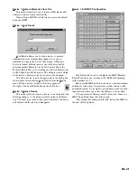
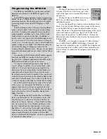
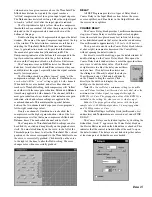
Like all detail windows, the name of the window is
displayed at the top. The edit boxes at the bottom of the
window show the current
Low Cut
and
High Cut
frequency
settings in Hertz. To edit the current values, click the up or
down arrows, or click in the edit box to display the cursor and
type a new value. The
High
and
Low Cut
filters are fixed
Butterworth, 24 dB/Oct. (4
th
order) filters.
The
Bypass
check boxes on the High and Low Cut detail
window turn the filters completely off. Note that this is
not
equivalent to simply setting them to their highest (20 kHz)
and lowest (20 Hz) frequency settings. Toggling these
Bypass
check boxes provides an easy way to compare
filtered versus unfiltered responses,
just be sure you don’t
cause any damage by bypassing the high or low cut filters.
Filter Bypassing is never ramped.
Adjusting the filter frequency settings is also possible if
you click and drag directly on the graphed curve itself. You
must click directly on the curve’s downward slope, on the
high or low frequency side, to successfully grab the curve and
alter the settings. The curve changes color when successfully
“grabbed” and the 3 dB down point of the curve snaps to your
cursor’s position. This 3 dB down point defines the frequency
setting for each filter.

