Manual-16
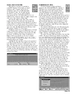
EXTENDED PARAMETRIC (PEQ+)
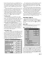
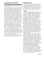
Some DSP Programs provide “Extended”
Parametric EQ, abbreviated
PEQ+
. Extended
parametric simply means that two of the available
PEQ filters contain extended capabilities. These
two special PEQ filters support various EQ filter
types, such as high pass (
HP
) or low pass (
LP
)
Linkwitz-Riley, Butterworth or Bessel filters, these are
abbreviated
LR
,
BW
and
Bsl
, respectively. Different slopes
for each of these filter types are also available, allowing
12
dB/Oct.,
18
dB/Oct. and
24
dB/Oct. filter implementations
(2
nd
, 3
rd
or 4
th
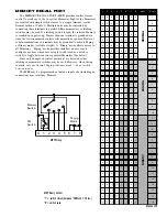
order), where applicable. In any extended
parametric, only the
first
and
last
filters contain the extended
capabilities; 1 and 4, in the above example screen.
The purpose of Extended Parametric is to give the RPM
26i the capability to implement up to a 6-way crossover.
Since each PEQ+ output can implement any crossover
frequency range, treating each output as its own crossover
band, provides multi-way crossovers.
Hint:
For midband crossovers, use 2 bands with one set
for
LP
, the other set for
HP
and overlap them.
Note:
Operation of Extended Parametrics (PEQ+) is
exactly like regular parametrics (PEQ),
the only difference is
when you choose
Cut
,
LR
,
BW
or
Bsl
filter types for a given
filter, the
Level
and
BW(Q)
settings for that filter have no
effect and are ignored by RaneWare.
The
Shelving
filter type
also ignores the
BW(Q)
setting.
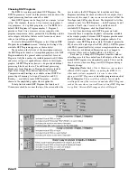
The
Filter Type
selection box is edited by clicking the
down arrow and selecting a new
Filter Type
such as
Low
Shelf
,
High Cut
or a
Normal
parametric filter. (See the
Extended Parametric section below for additional filter types
such as Linkwitz-Riley, Bessel and Butterworth filters.)
Those systems that require constant directivity horn equaliza-
tion can use the
CD Horn
EQ
Filter Type
(in combination
with other PEQ filters) to achieve the appropriate EQ for the
combination of horn and compresssion driver you are using.
For optimum frequency response, use an analyzer to achieve
the best possible horn EQ compensation.
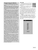
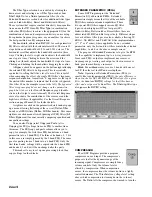
The bandwidth, abbreviated
BW (Q)
, for each parametric
EQ filter is edited with the horizontal scroll bar. There are 80
steps between a bandwidth of 0.036 and 2.543 octaves. The
horizontal scroll bar adjusts the bandwidth control in three
ways. Clicking the left or right arrows adjusts the bandwidth
one step at a time. Clicking between the arrows and the
sliding box (thumb) adjusts the bandwidth 10 steps at a time.
Clicking and holding the thumb allows dragging the control.
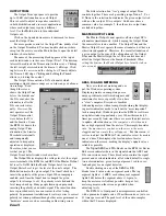
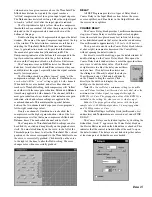
A
Bypass
check box appears on the bottom right allowing
the selected PEQ filter to be bypassed. This is essentially
equivalent to setting that filter’s level to zero. This is useful
when comparing the effect of a single PEQ filter’s frequency
response contribution. A small red ‘
X
’ appears over the top of
the circled filter number to indicate that the filter is bypassed.
(See filter #4 on the example screen to the left.)
The bypassed
filter’s response graph does not change on the parametric
graph, but it does on the
Overall Response
graph
(double-
click on the Output’s screw terminal). The Overall Response
curve also shows the contributions of the crossover and the
high/low cut filters (if applicable). See the Overall Response
section on page Manual-20 for further details.
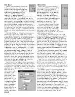
A right mouse click on the parametric detail window pops
up a menu allowing flattening of the
current
(
Flatten Filter
Level
) or
all
PEQ filters (
Flatten All Filter Levels
). This same
right mouse click menu allows bypassing all PEQ filters (
All
Filters Bypassed
) for conveniently comparing equalized and
unequalized settings.
You can also
Copy
(select
Copy
)
and
Paste
(
after
Copy
ing) the PEQ settings from one PEQ to another from
this menu. The PEQ copy and paste scheme allows you to
copy, for example, the first three PEQ bands from a 6 band
parametric into a 3 band PEQ. The three extra bands, 4, 5 & 6
in this case, are simply ignored by the 3 band PEQ. The same
goes for pasting from a 3 band into a 6 band PEQ. Only the
first three bands’ settings will be copied into the 6 band PEQ
and bands 4, 5 and 6 will be unchanged after the paste.
This makes it easy to set up one processing block, then
copy settings to other blocks.
COMPRESSOR
Most DSP Programs provide a program
compressor on each input. The compressor’s
purpose is to alter the dynamic range of the
incoming signal. Compressors are simply fancy
volume controls. Only the volume level is
altered by compression. When compression
occurs, the compressor turns the volume down in a tightly
controlled manner. The
Threshold
is a voltage level setting
above which compression (or turning down the volume)
occurs. The
Ratio
tells the compressor how much to turn the


