What is De-Essing?
In a nutshell, de-essing is noth-
ing more than attenuation at
specific frequencies. Sibilance
(that annoying hi
ssss
ing of “ess”
sounds that exhibits itself in
some peoples’ speech) manifests
itself as an increased level,
normally in the 3.5 kHz range.
However, this frequency may vary
from individual to individual,
hence the de-esser frequency
adjustment on the VP 12.
Large amounts of overall com-
pression can actually accentuate
sibilant sounds. This not only
upsets the balance between high
and low frequency speech compo-
nents, but can drive the sound
system into distortion.
Therefore, the best approach to
controlling sibilance is a circuit
that is adjustable to engage at
and above specific frequencies.
The characteristics of sibilance
demand a circuit with a fast
attack time and slow release time
to ensure a smooth inaudible
transition between the gain-
reducing state and the constant-
gain condition.
Through exhaustive testing of
currently available de-esser
circuits in other manufacturers’
products, Rane found that most
exhibit unwanted artifacts such
as common compressor “pump-
ing” and “breathing”. Some
exhibit 180° phase errors as well
as uneven frequency responses
(as much as +3 dB) at the de-
esser corner frequency.
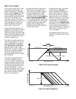
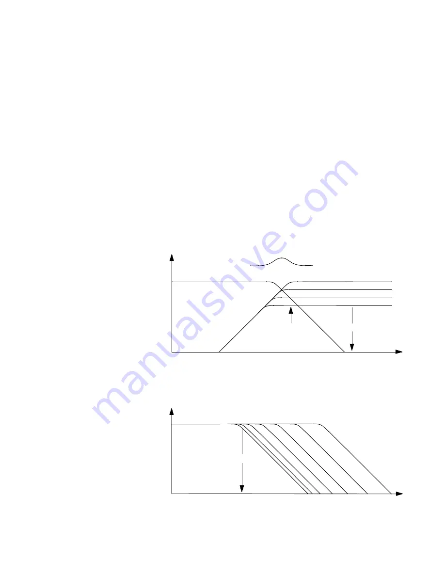
Rane De-Esser Response
Other De-Esser Response
Deciding that there had to be a
better way to accomplish sibi-
lance control, the Rane engineer-
ing team designed and imple-
mented a totally new circuit
utilizing a revolutionary
adaptive
servo controlled sliding band
circuit. Excellent buzz-words, but
in simple English this means that
instead of frequency dependent
compression, we designed a
sliding band filter that responds
quickly and quietly.
The band pass filter, controlled
by the de-esser
FREQUENCY
control, selects the frequencies
above which sibilance resides,
and since the filter is out of the
signal path and in the detector
path only, there are no summing
or gain errors. The voltage con-
trolled 6 dB per octave sliding
band filter has an
adaptive ratio
that allows a quick response, but
when it starts to attenuate the
unwanted sibilance, the response
slows down, providing a mini-
mum of artifacts.
The graphs below visually dem-
onstrate the new way versus the
old way.
Amplitude (dB)
Frequency (Hz)
20 Hz
20 kHz
+3 dB
180 out of phase
compression levels
low pass filter
o
high pass filter
sum error
sibilance frequency
Amplitude (dB)
Frequency (Hz)
20 Hz
20 kHz
sibilance frequency
Summary of Contents for VP 12
Page 1: ...VP 12 VOICE PROCESSOR...

