background image

108367

IMPORTANT SAFETY INSTRUCTIONS

For the continued safety of yourself and others we recommend that you read the following 

safety and installation instructions. Keep this document in a safe location for future reference. 

Please heed all warnings and follow all instructions.

Do 

not 

use this equipment in a location where it might become wet. Clean only with a damp 

cloth.

This equipment may be installed in an industry standard equipment rack. We recommend that 

all mounting holes be used, providing the best physical support. The equipment may be used as 

a table top device, although stacking of the equipment is dangerous and not recommended.

Do not directly block any of the ventilation openings. If rackmounting, please provide adequate 

ventilation. Equipment may be located directly above or below this unit, but note that some 

equipment (like large power amplifiers) may cause an unacceptable amount of hum or may 

generate too much heat and degrade the performance of this equipment.

Protect the power cord and plug from damage caused by being walked on or pinched. Protect 

the line cord, where it exits the unit, from excessive strain. Only use attachments and acces-

sories specified by Rane.

Unplug this equipment during lightning storms or when unused for long periods of time.

Refer all servicing to qualified service personnel. Servicing is required when the apparatus has 

been damaged in any way, such as power supply cord or plug damage, spilled liquid, fallen 

objects into an opened chassis, exposure to rain or moisture, a dropped unit, or abnormal 

operation.

Summary of Contents for VP 12

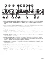
Page 1: ...VP 12 VOICE PROCESSOR...

Page 2: ...ilationopenings Ifrackmounting pleaseprovideadequate ventilation Equipment may be located directly above or below this unit but note that some equipment like large power amplifiers may cause an unacce...

Page 3: ...e MAIN OUTs to either a MIC or LINE level output depending on your driving requirements The AUX OUT of the VP 12 is only line level Plug the included power supply see italics below into the VP 12 The...

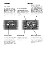
Page 4: ...the full CCW position the LOW CUT filter is essentially out of the signal path 6 HI CUT filter This control defines the high cut off frequency In the full CW position the HI CUT filter is essentially...

Page 5: ...f compression once the threshold has been exceeded Full CCW rotation effectively disables the compressor y GAIN REDUCTION METER This seven segment meter indicates the amount of signal reduction below...

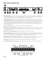
Page 6: ...th screw terminals and XLR jacks can be used at the same time 5 MAIN and AUX screw terminal outputs Deliver the same outputs as the XLR connectors above 6 Screw terminal patch strip Configured from th...

Page 7: ...e OL LED We call this tickling the overload This may be illegal in your jurisdiction so please check your local authorities If only the LINE EXPAND input is to be used set the front panel switch to LI...

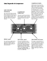
Page 8: ...switch is out Set the COMPRESSOR THRESHOLD control to 20 and the COM PRESSOR RATIO to about 1 6 1 Now apply the largest signal to be unaffected by the COMPRESSOR This establishes the highest signal le...

Page 9: ...s off at a rate of 12 dB per octave The frequency designator 10 Hz to 250 Hz is the corner frequency at which the low end starts to roll off Turned all the way counterclockwise the low cut filter is e...

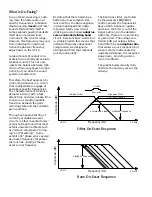
Page 10: ...breathing Some exhibit 180 phase errors as well as uneven frequency responses as much as 3 dB at the de esser corner frequency Rane De Esser Response Other De Esser Response Deciding that there had t...

Page 11: ...d signal Gate Expander Compressor COMPRESSOR RATIO Determines by how much the gain is held in check Remember higher ratios mean the compres sor works harder essentially turning it into a limiter Ratio...

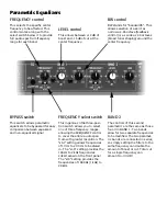
Page 12: ...ting provides the frequencies of 1000 Hz 1 kHz to 20 kHz BYPASS switch This switch allows parametric equalizers to be bypassed for easy comparison between equalized and non equalized signal BAND 2 The...

Reviews: