background image

WIRING INSTRUCTIONS

ALL WIRING MUST BE CARRIED OUT IN ACCORDANCE WITH CURRENT IEE WIRING REGULATIONS.

The boiler must be installed by a qualified competent tradesman in accordance with these instructions and drawings to ensure correct operation.

Check the main incoming supply to the property to ensure there is sufficient current and voltage for the size of the boiler or boilers to be installed. 
Remember to also take account of the supply requirements for the rest of the property. Ensure the correct cable size is used to feed the boiler.

Ensure the installation complies with current IEE regulations BS7671:2008.

A double pole RCD with a trip level sensitivity of 30mA and capable of breaking the full load current to BS EN 61008:1994, must be used. 
In order to provide a means of isolation, the boiler must be connected to the supply through a double pole linked switch with a 
minimum contact gap of 3mm in all poles. The RCD is suitable for this requirement if it is mounted in close proximity to the boiler.
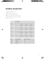
A correctly rated MCB must be used in the supply, see Technical Specifications (see page 19). An additional 3A supply is required for 
the controls etc. NOTE, a blank must be fitted between each MCB to provide ventilation, check with the MCB manufacturer/supplier. 

NOTE:

 The high current mains supply 

MUST NOT

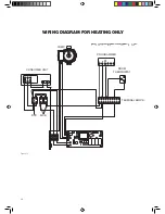
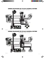
 be routed through the programmer, controls etc. Follow the wiring diagrams. Use a standard 

programmer, room thermostat, etc. 
The high current switching is carried out inside the boiler, only standard switched live (low current) control signals are supplied by the 
programmer etc.

ELECTRICAL CONNECTIONS

Access can be gained to the boielrs electrical connections by removing the front panel. The earth lead is removed from the front cover by depressing 
the release button on the connection to the cover.

IT IS IMPORTANT THAT THE EARTH CONNECTION SHALL ALWAYS BE RECONNECTED WITH THE RELEASE BUTTON 
FITTED INWARDS AND EARTH BOND TESTED AFTER ANY MAINTENANCE HAS BEEN CARRIED OUT. 

THESE CONNECTIONS MUST BE TIGHT. LOOSE CONNECTIONS COULD CAUSE A FIRE OR BURNING AT MAIN TERMINAL 
CONNECTOR AND IS NOT COVERED BY THE WARRANTY.

1. MAIN POWER. Main power-supply cables. Using the correct rated cables, connect the main terminals live, neutral and earth directly to the isolation 
switch,. Do not connect the power through the programmer, thermostats etc. The main power terminals in the boiler are suitable for cables up to 16mm.

2. CN1: CONTROL SIGNAL. Connect switched live to ‘D’ and neutral to ‘N’ on the control terminal block in the boiler to the switched live and neutral 
from the programmer control circuit. A neutral must be connected, as this control signal is optically isolated from the main supply in the boiler and will 
not run without a neutral.

3. CN2: PUMP CONNECTIONS. The supply to the pump must be connected to the ‘PUMP’ terminal on the control terminal block in the boiler. This 
supply is fused in the boiler at 2A.

CONNECTIONS FOR 2 OR MORE BOILERS

1. Main power-supply cables. Connect each boiler to its supply live, neutral, and earth, as described above. The supplies to each boiler can be on 
different phases if using a 3-phase supply.

2. CN1: Control signal. Join all the boiler ‘D’ terminals on the control terminal block together, and then connect them to the switched live control 
signal to the programmer control circuit. Connect all the boiler ‘N’ terminals on the control terminal block together and then to neutral on the 
programmer control circuit.

3. CN2: Pump connections. The pump must be connected through a relay assembly to ensure that the pump always operates if any one boiler is 
running. Check the main electrical power connections are tight. Loose connections can cause a fire and will invalidate the warranty. The control 
DEMAND signal is optically isolated from the main boiler supply to enable different phases to be used between boilers. The control signal required to 
operate the boiler is 220v - 240v at a very low current typically 10mA.

12

Summary of Contents for Senator RFB006 6kW

Page 1: ...Models RFB006 6kW RFB009 9kW RFB011 11kW RFB012 12kW INSTALLATION AND USER INSTRUCTIONS March 2009 Issue No 3 www kingspanhws com...

Page 2: ...time of going to press however Kingspan reserves the right to change any information herein without notice Senator is a Trademark of Kingspan Plc Range Senator RFB 006 RFB 009 RFB 011 RFB 012 Your El...

Page 3: ...ber and 2 years on all other components In the event of a potential warranty claim always quote the boiler serial number No claims will be considered without this number The warranty covers the replac...

Page 4: ...NATOR FLOW BOILER Page 3 of 27 FLOW 22mm COMPRESSION RETURN NOT SHOWN ELECTRICAL CABLE ENTRY POINTS TOP SEALING GROMMET MAIN TERMINAL BLOCK MAIN POWER BOARD CONTROL PANEL FRONT COVER INSULATION PRODUC...

Page 5: ...BASIC INSTALLATION DIMENSIONS 120mm 120mm 100mm 900mm Fixing Centres 8 5mm 1050mm Cable Entry Knock Outs 1 x 25mm 2x 20mm Left Right Rear Fixing Centres Figure 2 5...

Page 6: ...mounted in an UPRIGHT position only with the electrical connections uppermost Any deviation from vertical is unacceptable The boiler must be fixed to a wall before connecting pipework When choosing th...

Page 7: ...be mounted in the return pipework pumping water upwards through the boiler Size the pump in the usual way and set to maximum to ensure sufficient flowrate The pump fitted to this system and controlled...

Page 8: ...ing the correct dosage of inhibitor must be added Fernox Superconcentrate or MB1 or Betz Dearborn Sentinel X100 can be used in most water areas however consult manufacturer s instructions and local wa...

Page 9: ...s Auto Air Vent 150mm maximum 150mm minimum Basic Plumbing Schematic Space heating only open vented DRAIN VALVE PUMP Automatic Bypass minimum of 2 metres Safety Controls Radiators Auto Air Vent 150mm...

Page 10: ...stem DRAIN VALVE PUMP Radiators Auto Air Vent Automatic Bypass minimum of 2 metres Cylinder 150mm minimum Basic Plumbing Schematic Space heating and hot water s plan system Figure 5 Figure 6 Open vent...

Page 11: ...m PIPE FLOW 12L MIN 28mm PIPE FLOW 24L MIN 35mm PIPE FLOW 36L MIN RETURN FLOW DRAIN VALVE AUTOMATIC AIR VENT 150mm minimum Automatic Bypass minimum of 2 metres 35mm 35mm 3 Boiler Plumbing Schematic Fi...

Page 12: ...CTED WITH THE RELEASE BUTTON FITTED INWARDS AND EARTH BOND TESTED AFTER ANY MAINTENANCE HAS BEEN CARRIED OUT THESE CONNECTIONS MUST BE TIGHT LOOSE CONNECTIONS COULD CAUSE A FIRE OR BURNING AT MAIN TER...

Page 13: ...1 Fully pumped system 2 Independent temperature and time controls for both heating and domestic hot water 3 Controls to interlock with the boiler TRV s alone do not comply 4 An automatic bypass is re...

Page 14: ...ns are made correctly check the main supply terminals in the boiler are tight close and secure the top front cover of the boiler MAIN TEST PROCEDURE Only after a satisfactory initial test proceed as f...

Page 15: ...to black grey to grey blue to blue and green to green and an insulation resistance greater than 2 Meg ohms between terminal and case If the elements are open circuit terminal to terminal or have short...

Page 16: ...NO NO NO NO NO YES YES YES YES APPROX 8 SECS YES Rectify supply fault Is there 230V AC at transformer TX1 on powerboard Is Fuse F1 OK rating 2 5A 20 X5 Replace powerboard Replace powerboard Is there...

Page 17: ...water in heater or no flow Check for water or flow 4 flashes Excessive current with relay s on Faulty Triac s Replace powerboard 5 flashes Excessive current with triac s on Faulty relay s Replace powe...

Page 18: ...output temperature less than 60 C NO Adjust output temperaure or flow minimum maintained Are elements within specification refer to manual page 5 NO Faulty elements Request service exchange boiler Ha...

Page 19: ...ire from main terminal block Remove 2 x screws from main terminal block to main terminal mounting Note the assembly position in relation to pipe Restrain power board assembly Remove four retaining scr...

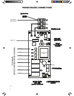
Page 20: ...Page 18 of 27 E LOWER TEMPERATURE SENSOR MANUAL RESET HIGH LIMIT CUT OUT SWITCHES CN14 CN12 PUMP EARTH TO ELEMENTS REFER TO INDIVIDUAL MODEL DIAGRAMS TO EARTH BOND BOLT N L Black N1 Grey N2 Blue N3 Gr...

Page 21: ...21 Heat Ouput Adjustment 60 C to 80 C Supply Green LED Demand Amber LED Heat Green Bar Graph Fault Red LED Powerboard COntrol Panel Diagram...

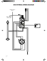
Page 22: ...22 REAR CHASSIS EARTH BOLT FRONT COVER EARTH 6kW Internal Wiring Diagram Page 19 of 27 6kW Internal Wiring Diagram L1 L2 N1 N2 Figure 9...

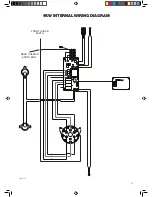
Page 23: ...Page 20 of 27 REAR CHASSIS EARTH BOLT FRONT COVER EARTH 9kW Internal Wiring Diagram 9kW Internal Wiring Diagram L1 L2 L3 N1 N2 N3 Figure 10 23...

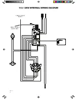
Page 24: ...11 12kW Internal Wiring Diagram REAR CHASSIS EARTH BOLT FRONT COVER EARTH Page 21 of 27 11 12kW Internal Wiring Diagram L1 L2 L3 L4 N1 N2 N3 N4 Figure 11 24...

Page 25: ...signal requires 200v 245v 50Hz DEMAND control input signal draws less than 0 25A 10mA typical Optical isolation Between the control signals and the boiler supply High limit switches trip 90 C 4 C No o...

Page 26: ...NG DIAGRAM FOR HEATING ONLY 10 10 4 4 1 1 2 2 3 3 7 7 5 5 6 6 8 8 9 9 ON ON L L N N CH CH PROGRAMMER CONSUMER UNIT MCB RCD PUMP ROOM THERMOSTAT TERMINAL BLOCK WIRING DIAGRAM FOR HEATING ONLY Figure 12...

Page 27: ...TERMINAL CONNECTORS WIRING DIAGRAM FOR Y PLAN CONTROL SYSTEM Figure 13 Page 25 of 27 MCB RCD L N 10 4 1 2 3 7 5 6 8 9 TERMINAL BLOCK N L ROOM THERMOSTAT CONSUMER UNIT ON L N ON OFF OFF CH HW CH HW PR...

Page 28: ...0 MM NYLON GABLE GLAND FBS0315 25 MM NYLON GABLE GLAND FBS0316 FIXING KIT 3 X NO12 X 50 SCREW PLASTIC WALL PLUG FBS0317 INSTRUCTION MANUAL FBS0318 MAIN TERMINAL INDICATOR LABEL FBS0319 CONTROL PANEL P...

Page 29: ...ve priority to the shower a simple relay is added as shown in diagram below When the shower is used the boiler will cease to operate When the shower is turned off the boiler operation will recommence...

Page 30: ...ntrol Where the operational load calls for a multiple boiler installation up to three number isolation relays are required to operate the pump To enable this connection Kingspan offer a multiple relay...

Page 31: ...31...

Page 32: ......

Reviews: